
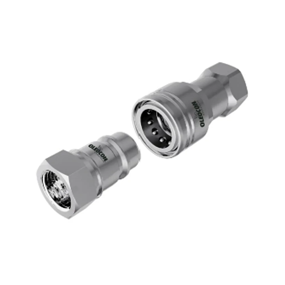
 Poppet type
6,3–50315bar
ISO 7241-A / B
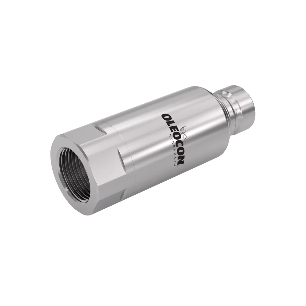
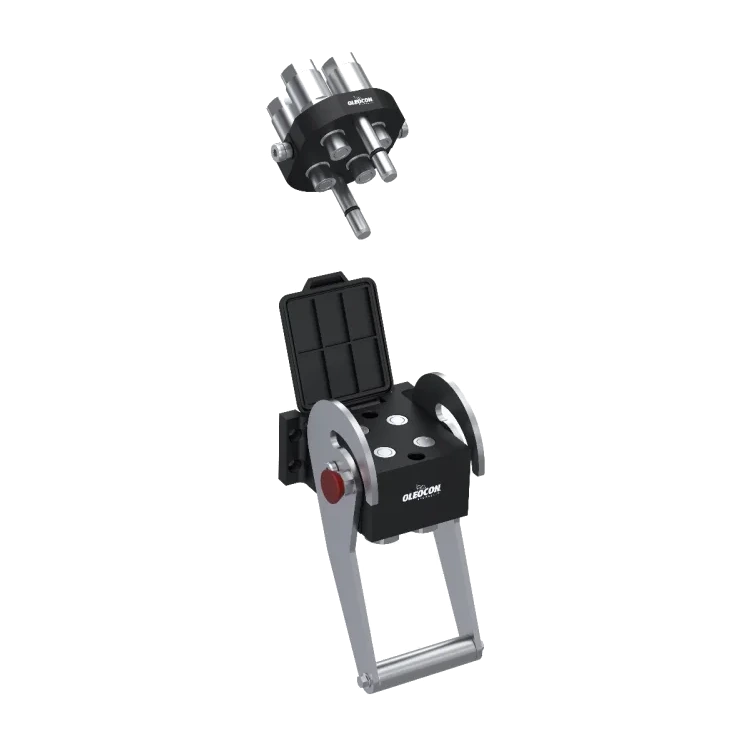
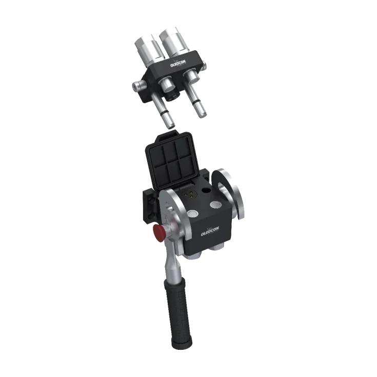
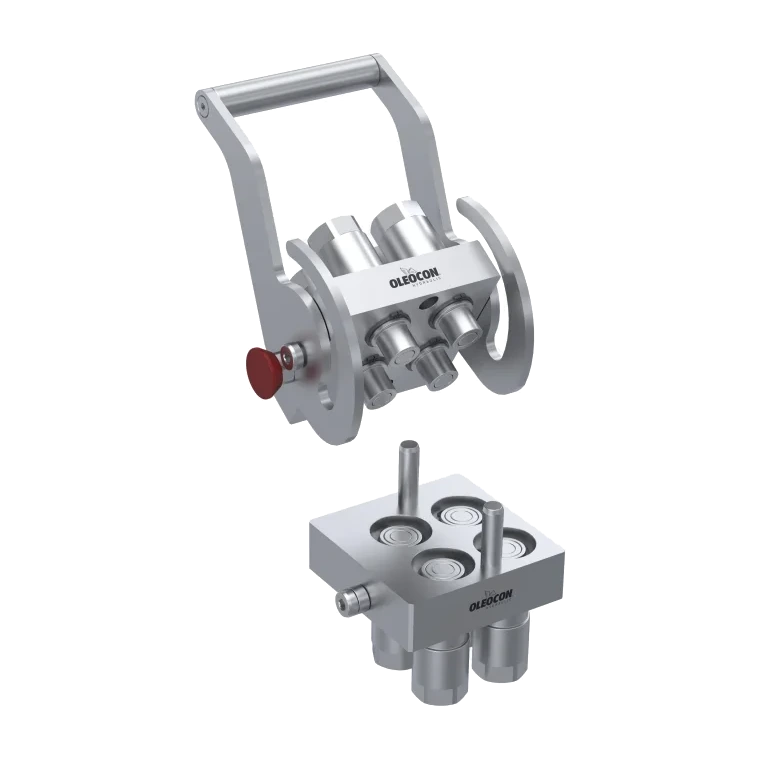
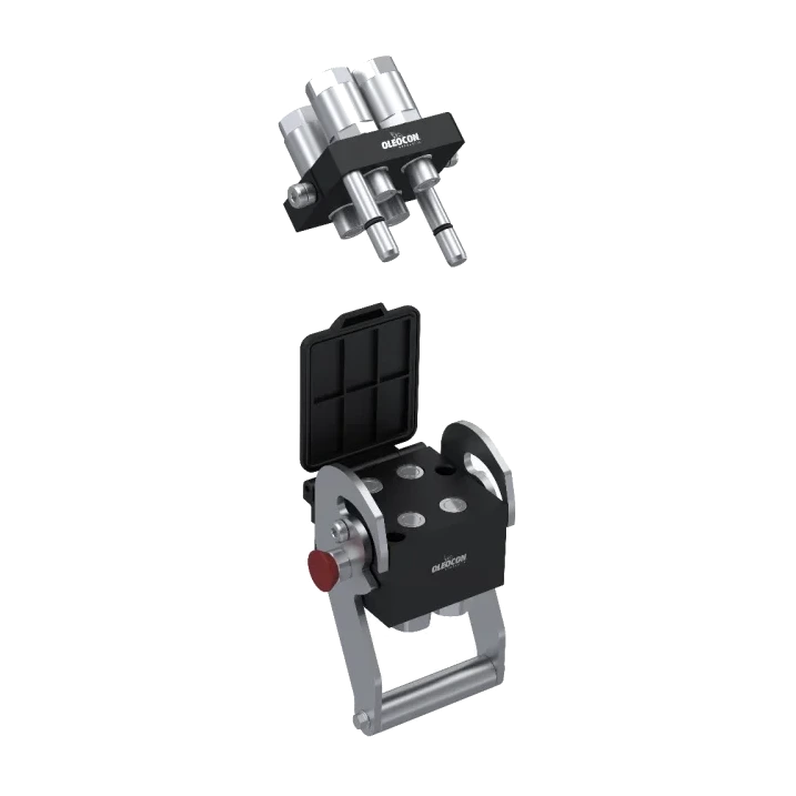
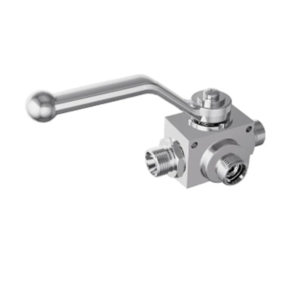
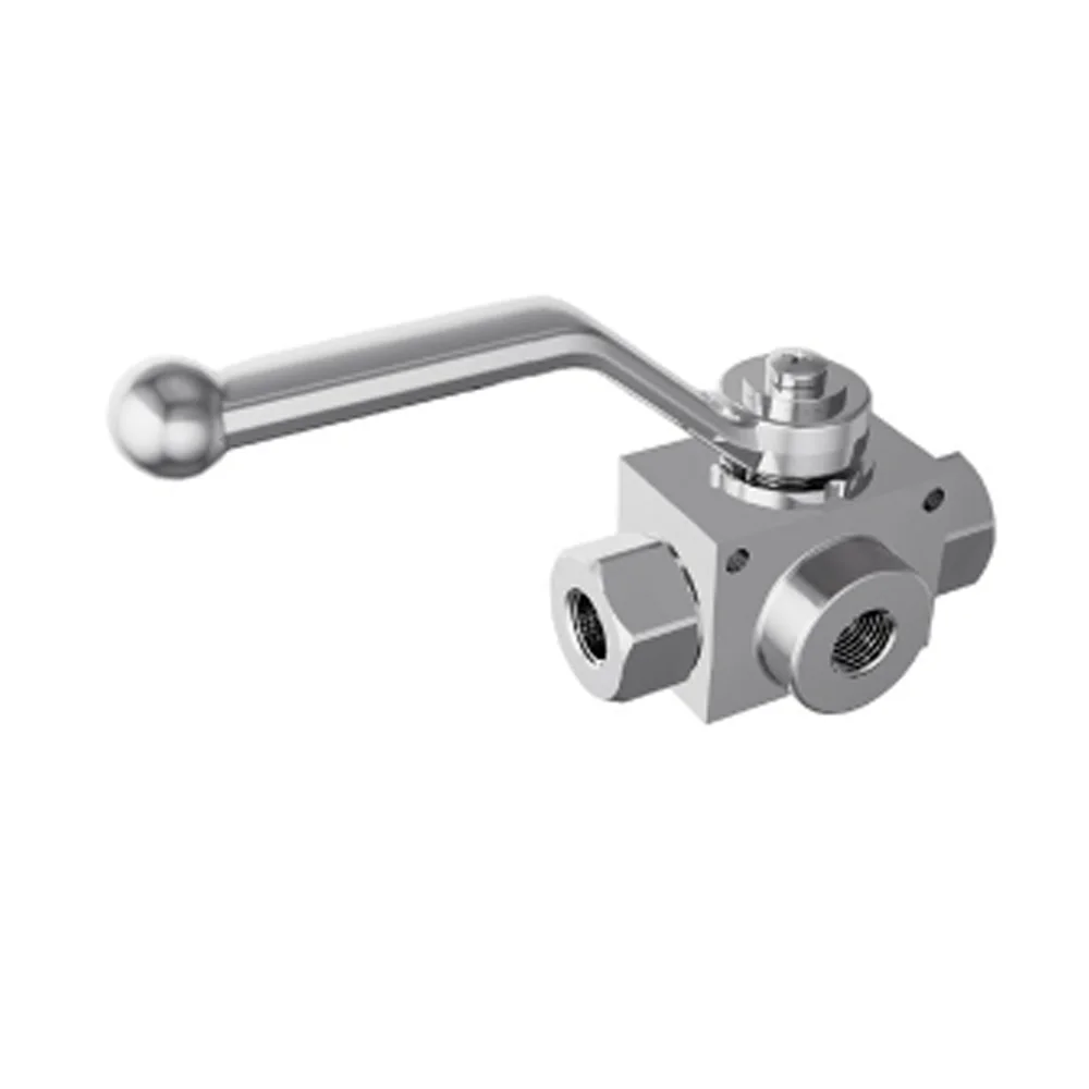
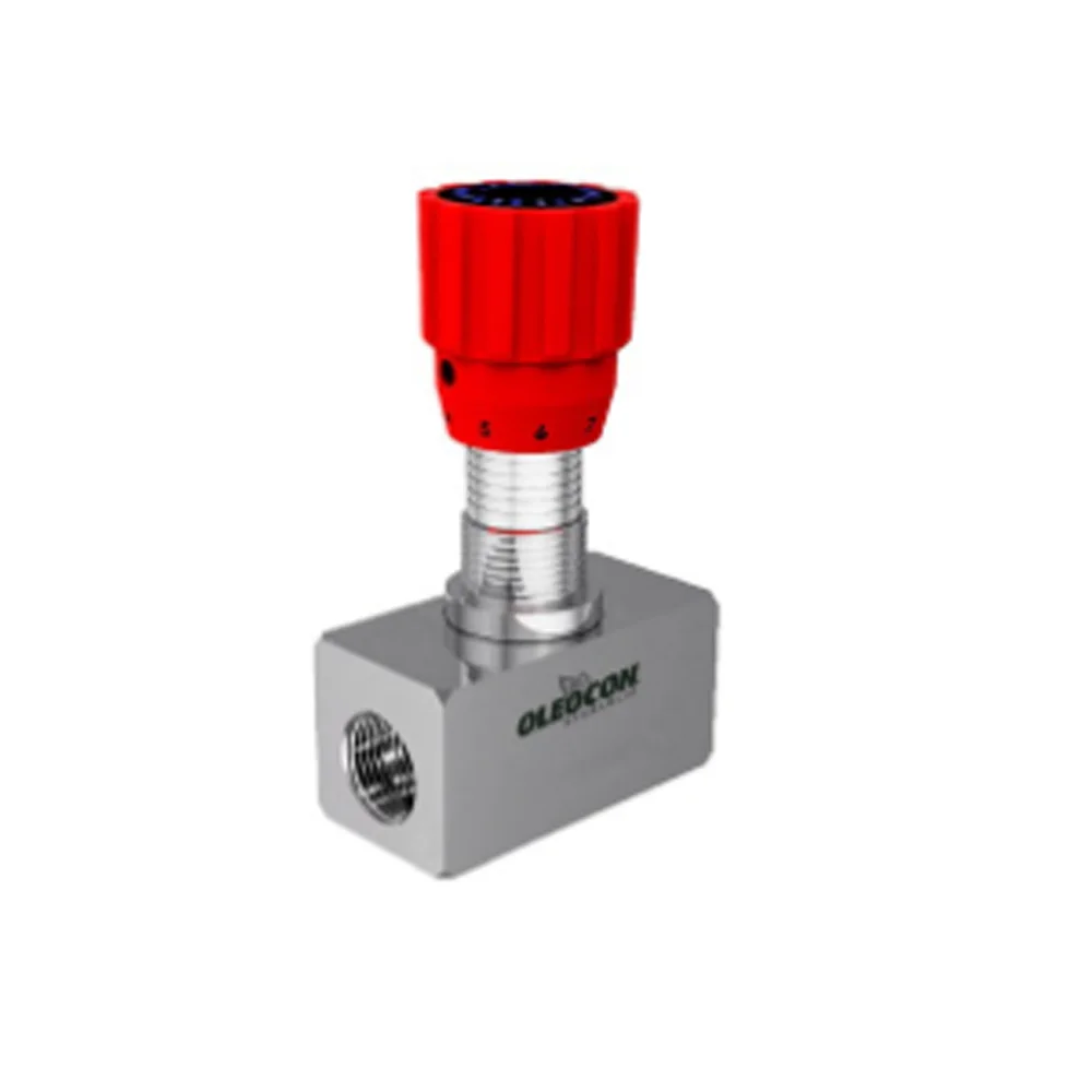
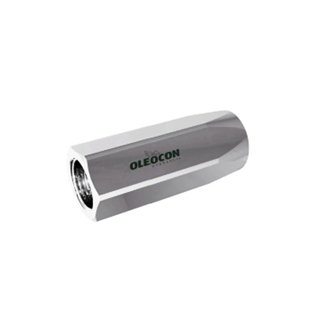
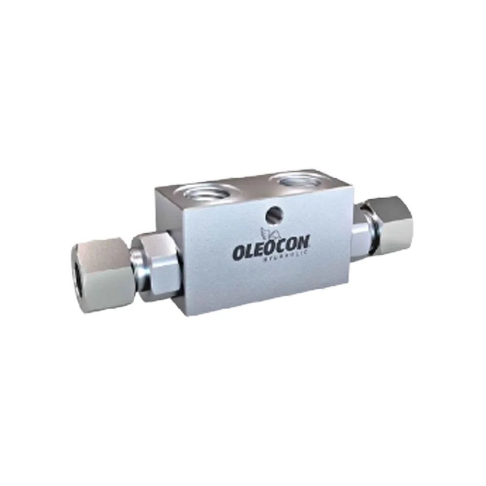
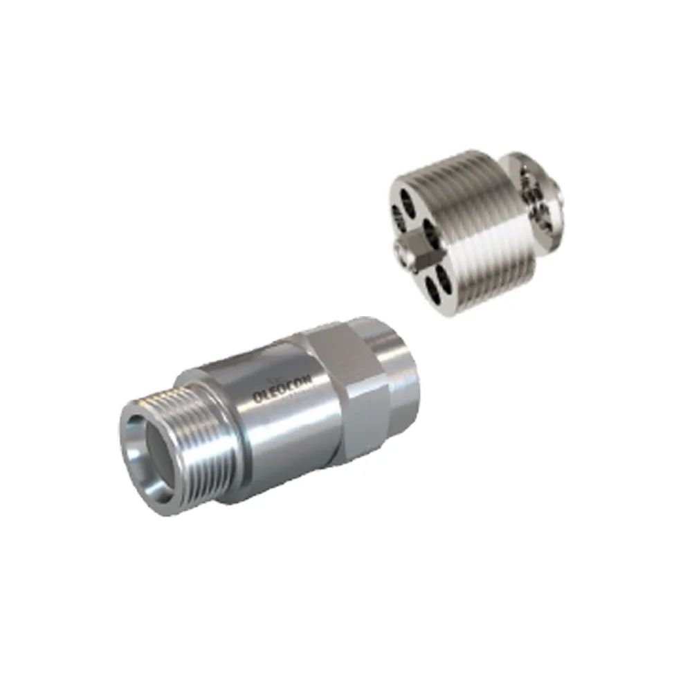
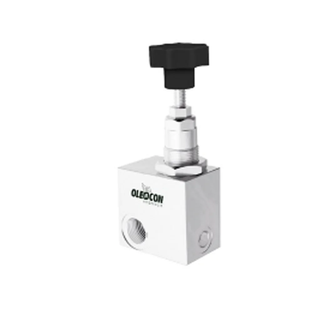
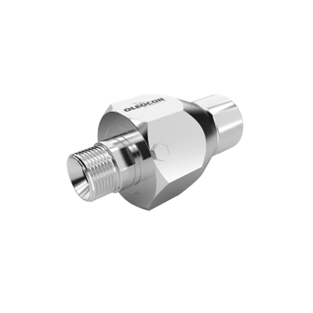
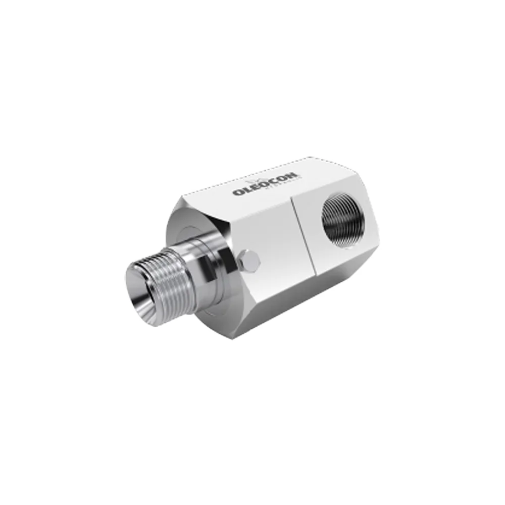
KV2 · Ball valve
2-wayMetricISO 8434-1
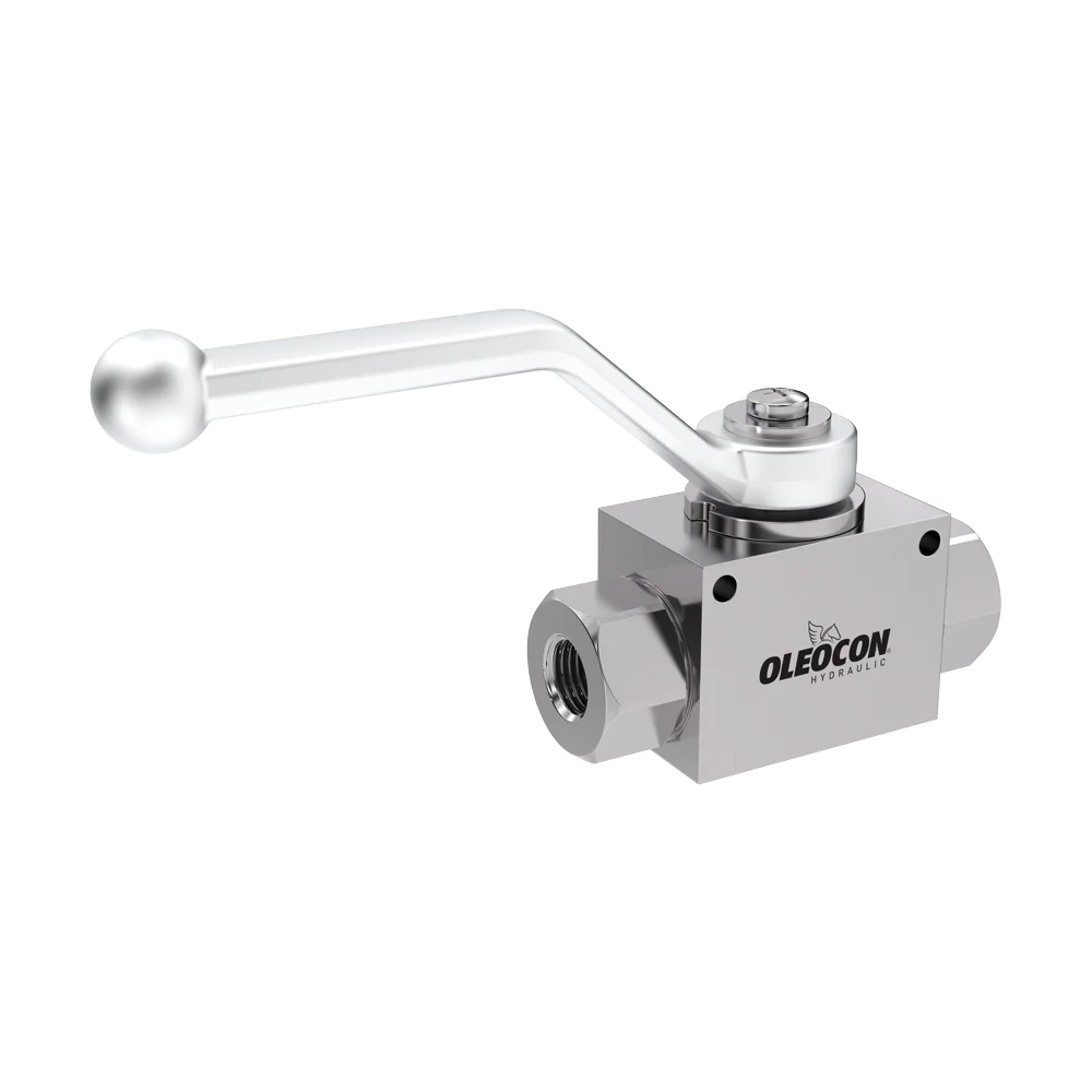
A 2-way hydraulic ball valve that opens and closes the flow path. It does not restrict flow, its full-bore design prevents cavitation, and it can be locked open or closed with the locking plate.
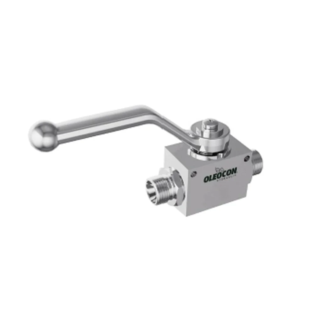
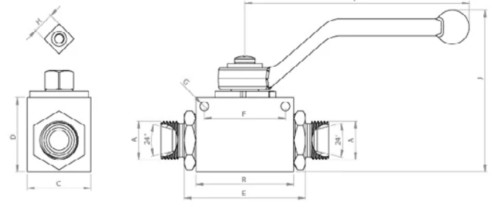
KV2-20-22L · Metric
Dimensions
KV2-20-22L and other products in body size DN20
Letters refer to the dimensions on the technical drawing. Click a code to open that product.
Performance
How much can KV2-20-22L take?
Operating conditions and sealing.
400bar
Max. working pressure · series maximum 500 bar
- Max. working pressure400 bar5802 psi
- Working temperature−20 / +100 °C
- Seal materialNBR (standard)FKM, PTFE, EPDM optional
- Lever movement90°fully open / fully closed
Available on request: Test pressureBurst pressureFlow rate / pressure drop (Kv)Lever turning torque
Request technical data
Where does the oil flow in each lever position?
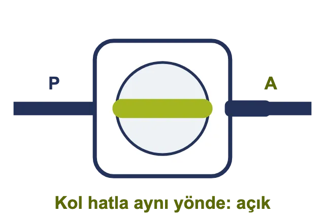
Open (P → A)
Oil passes unobstructed.
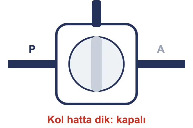
Closed
Flow is shut off completely.
Intermediate position
With the lever between the two positions, the valve is half open; do not leave it in this position and do not use it to adjust flow.
Lever direction
With the lever in line with the pipe, the valve is open; at right angles to the line it is closed; the position can be read from outside.
What is this valve made of?
Scroll the table sideways to see all columns
| Part | Material |
|---|---|
| Body | Steel · Zn-Fe (Cr III) plating |
| Side fitting | Steel · Zn-Fe (Cr III) plating |
| Ball | Steel · coated |
| Shaft (lever pin) | Steel · coated |
| Lever | Cast |
| Ball seat | Delrin (POM) |
| O-ring | NBR (standard) |
Maintenance and spare sealing parts
Sealing parts used in this body size.
Scroll the table sideways to see all columns
| Part | Material |
|---|---|
| O-ring 2 × 21 · 1 pc | 90 Shore |
| O-ring 2 × 26 · 2 pcs | 90 Shore |
| O-ring 2 × 33 · 2 pcs | 90 Shore |
| O-ring 3 × 14 · 1 pc | 90 Shore |
| Teflon ring 0.5 × 20.5 × 24.9 · 1 pc | PTFE |
| Ball seat | Delrin (POM) |
| Ready-made seal kit code | Pending |
Options for this product
Scroll the table sideways to see all columns
| Option | Details |
|---|---|
| Sealing | NBR standard · FKM, EPDM optional |
| Stainless steel body | AISI 316L · FKM seal · −20 °C / +200 °C · 250–400 bar |
| Locking | In the open or closed position with the locking plate |
| Limit switch / actuator | Pending |
How is it manufactured and how is it inspected?
-
01
Machining
The body, side fittings, ball and lever pin are machined on CNC machines at Oleocon.
-
02
Measurement
The body, side fitting and ball are measured after machining: visual inspection, optical measurement, gauges, dial indicator, height gauge, caliper and fitting gauge are used.
-
03
Plating and incoming inspection
Plated parts are inspected again before they go to assembly.
-
04
Assembly
The body is marked; the lever pin, ball, O-rings, PTFE and side fittings are installed; the fitting is tightened and the lever is tested; the handle is fitted.
-
05
Testing
The assembled valve goes through the test step.
-
06
Packaging
The valve that passes the test is packed.
What to watch for with this valve
CautionRead before installation and use
Do not leave in an intermediate position
Always turn the handle fully to the position between the stops.
Do not disassemble under pressure
Release the line pressure before disassembling the valve.
Do not weld on the side fittings
Heat damages the O-rings and ball seats.
Other KV2 products with the same body size
Same mounting dimensions, only the connection thread changes · 4 connection options
DN20body sizesame body, different connection thread
What does KV2-20-22L mean?
KV21
Series
2-way ball valve
202
Body size
DN20
22L3
Thread
M30×2 (22L)
DIN 2353 metric tube
Applications
Instructions and warnings
Before use.
Correct use
For long life and reliable sealing
- Keep the flow rate within normal valuesMake sure the flow rate is within normal values.
- Protect against abnormal conditionsDo not expose to oscillation, pressure shocks, water hammer, cavitation, or solid and abrasive particles.
- Use fully open or fully closedA ball valve works fully open or fully closed; in a half-open position the ball seat wears and sealing is lost. Use FUV / FCV for flow adjustment.
- Turn the handle all the way to the stopsAlways turn the lever between the stops to the fully open or fully closed position; the ball seat of a valve left in an intermediate position will be damaged.
- Turn slowly under pressureClosing suddenly at high pressure creates a pressure surge in the line; turn the handle slowly and in a single movement.
- Operate the valve from time to timeAfter a long period of inactivity, the handle feels stiffer the first time it is turned; open and close the valve at regular intervals.
Warnings
Read before installation and use
- !Do not touch the valves when the operating temperature is below -20 °C or above +50 °C.
- !Make sure the system pressure is below the maximum working pressure.
- !Make sure all connection surfaces are clean so that dirt and dust do not build up in the circuit.
- !Make sure the mounting parts are on the same axis and fully connected.
- !Make sure the Oleocon product you have selected is suitable for your system's temperature, material and pressure requirements.
- !For any other questions, contact the Oleocon technical support team.
Other sizes of this type
- DN10Ø 10 mm M12×1,5 (6L)KV2-10-6L
- DN10Ø 10 mm M14×1,5 (8L)KV2-10-8L
- DN10Ø 10 mm M16×1,5 (10L)KV2-10-10L
- DN10Ø 10 mm M18×1,5 (12L)KV2-10-12L
- DN10Ø 10 mm M14×1,5 (6S)KV2-10-6S
- DN10Ø 10 mm M16×1,5 (8S)KV2-10-8S
- DN10Ø 10 mm M18×1,5 (10S)KV2-10-10S
- DN10Ø 10 mm M20×1,5 (12S)KV2-10-12S
- DN12,5Ø 12,5 mm M22×1,5 (15L)KV2-12-15L
- DN12,5Ø 12,5 mm M26×1,5 (18L)KV2-12-18L
- DN12,5Ø 12,5 mm M24×1,5 (16S)KV2-12-16S
- DN20Ø 20 mm M30×2 (20S)KV2-20-20S
- DN25Ø 25 mm M36×2 (28L)KV2-25-28L
- DN25Ø 25 mm M45×2 (35L)KV2-25-35L
- DN25Ø 25 mm M52×2 (42L)KV2-25-42L
- DN25Ø 25 mm M36×2 (25S)KV2-25-25S
- DN25Ø 25 mm M42×2 (30S)KV2-25-30S
- DN25Ø 25 mm M52×2 (38S)KV2-25-38S