
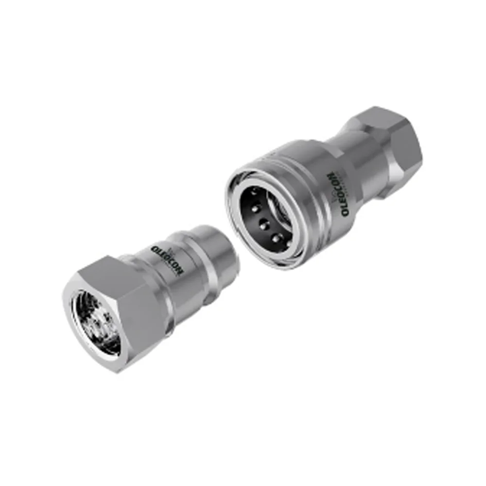
 Poppet type
6,3–50315bar
ISO 7241-A / B
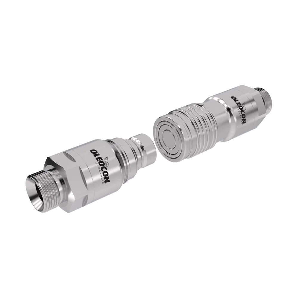
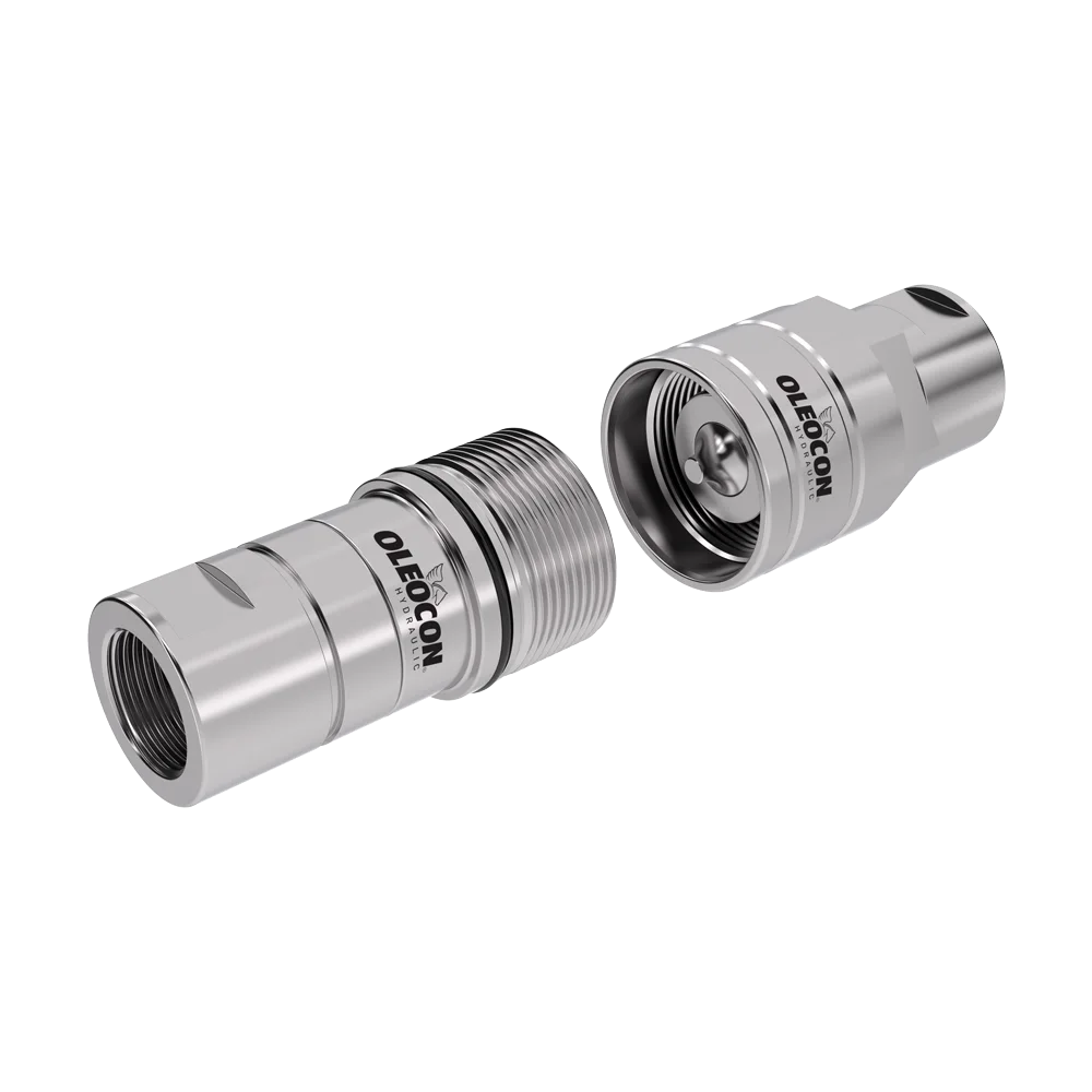
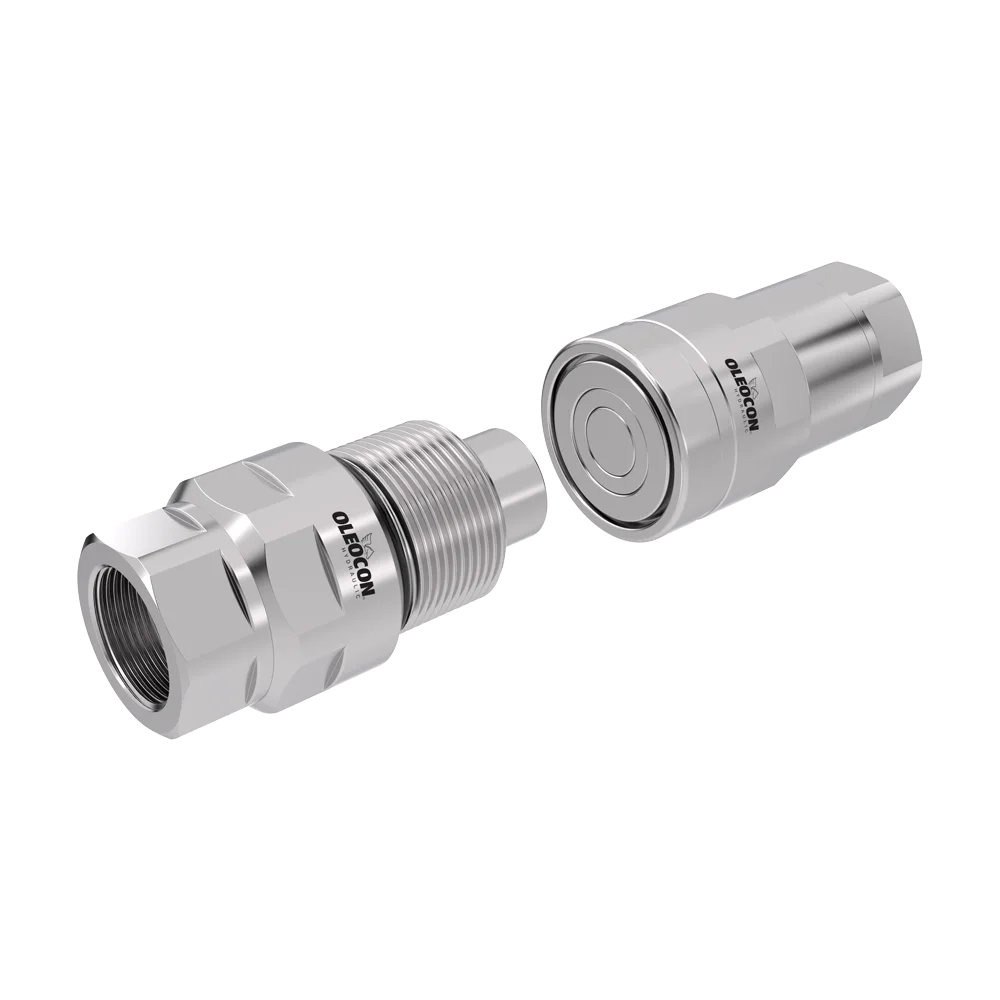
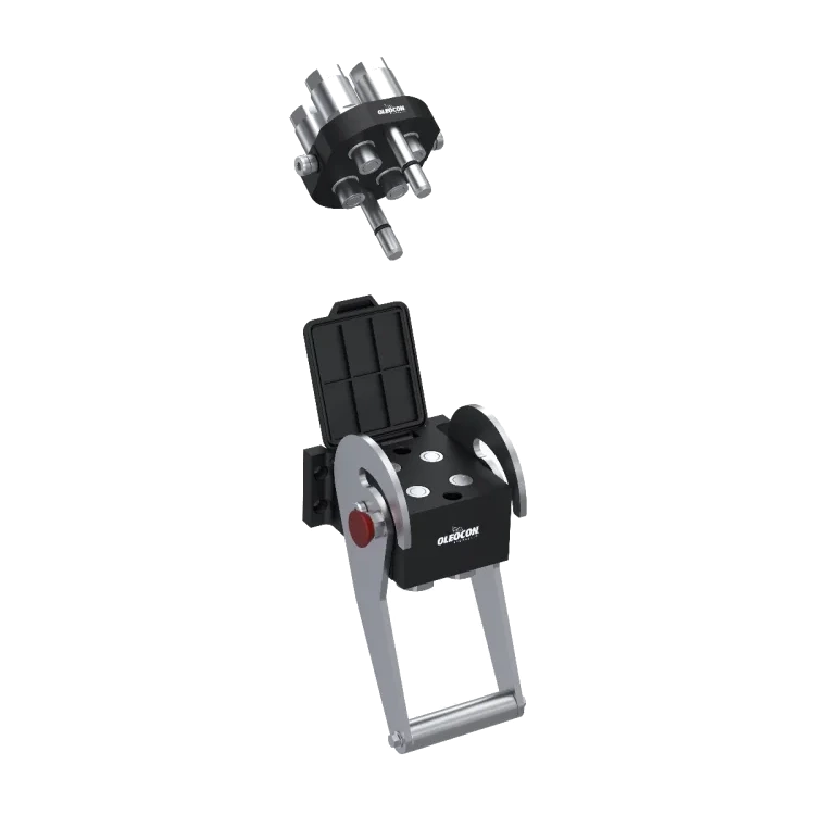
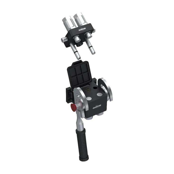
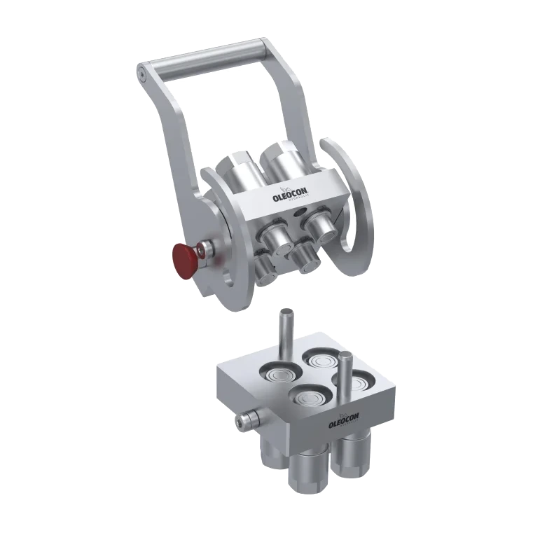
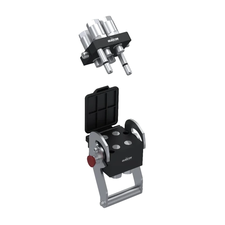
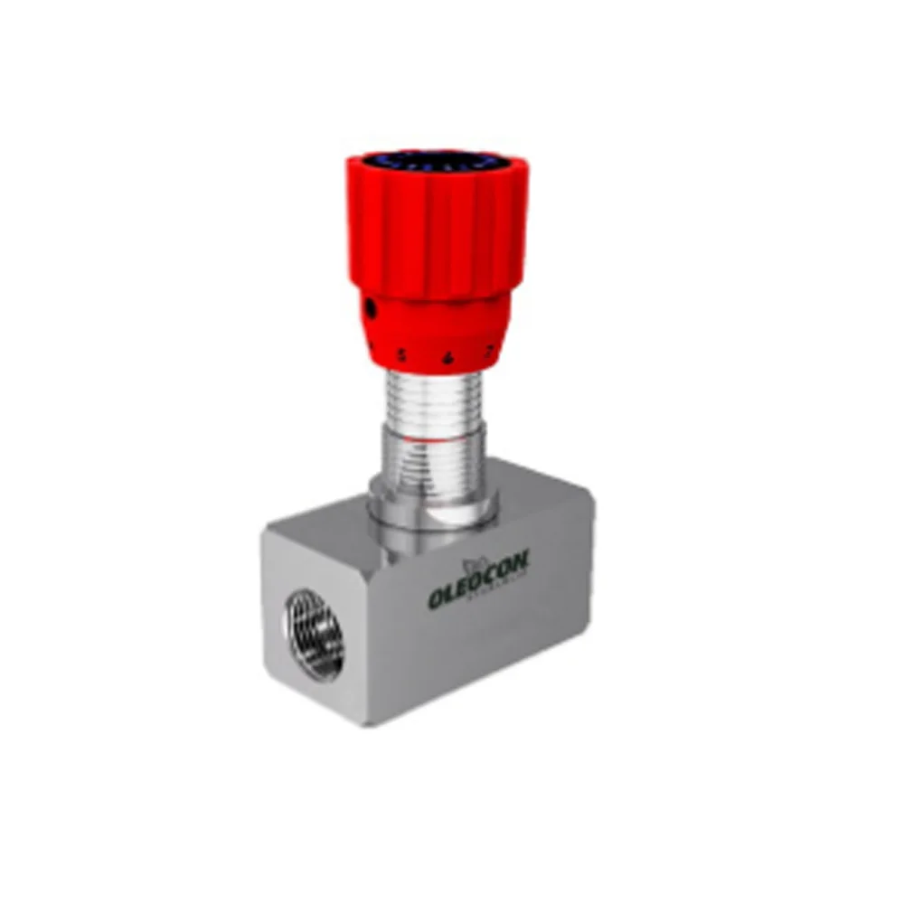
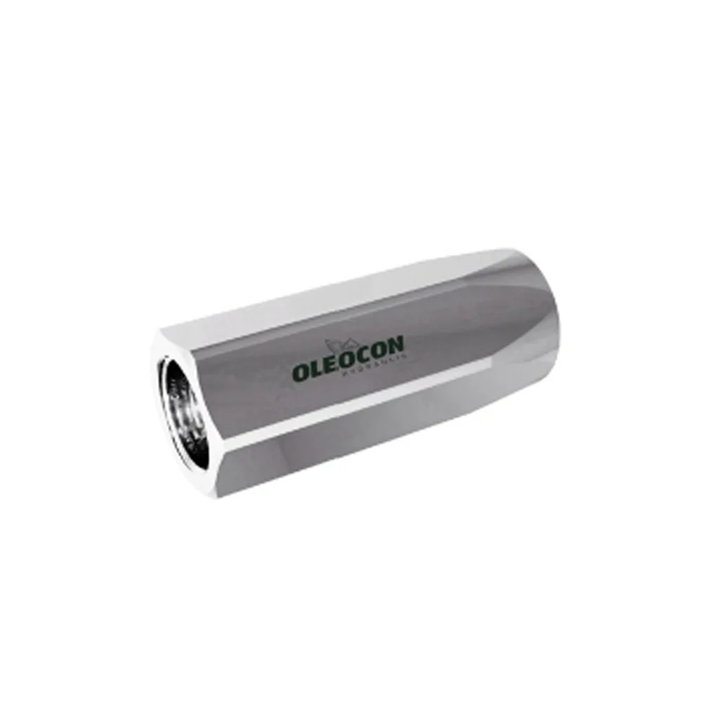
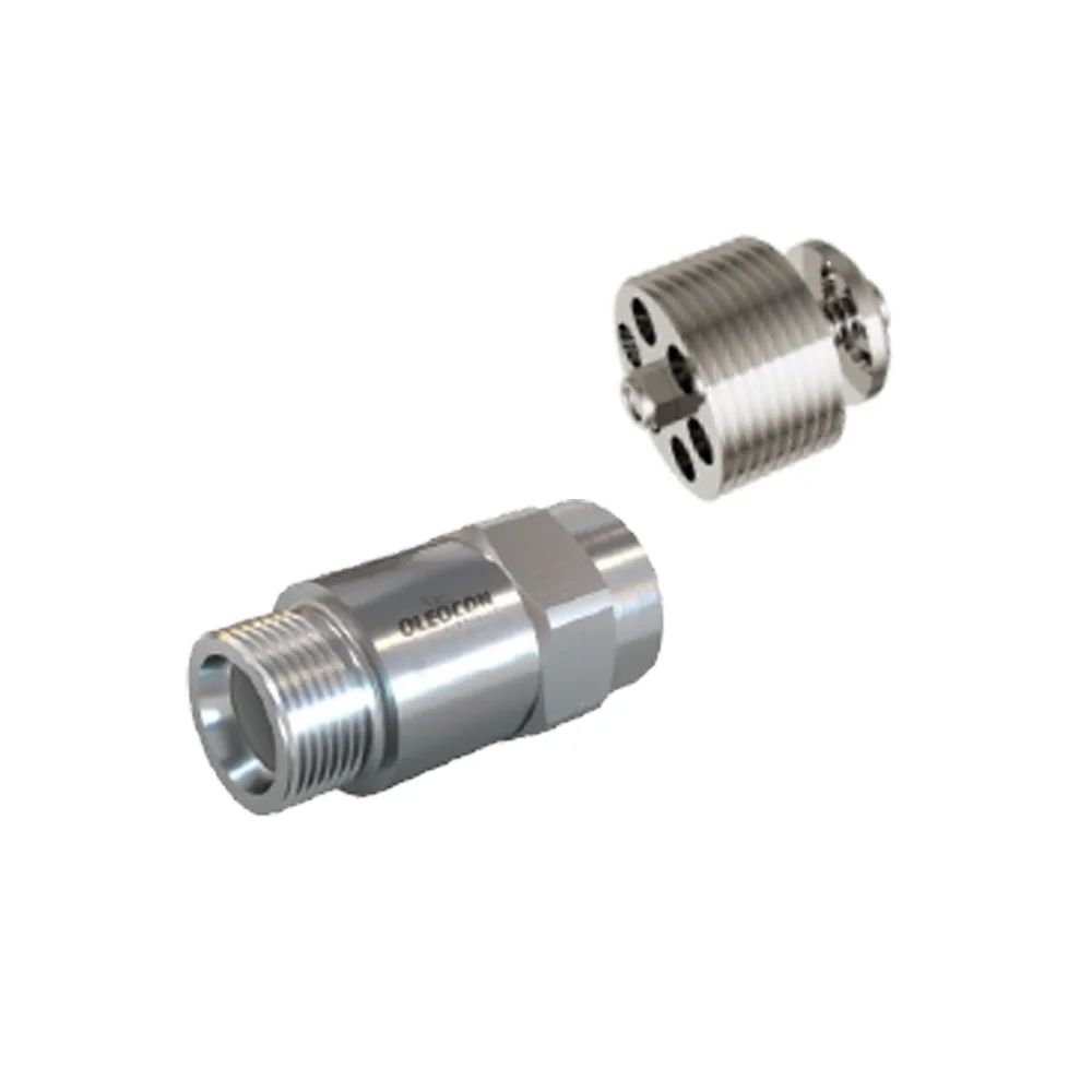
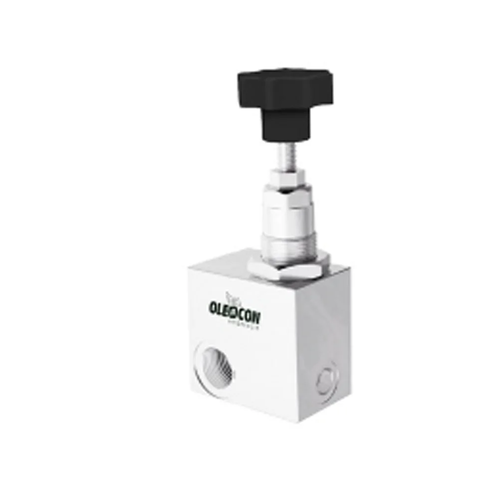
Auxiliary Valves
TLV
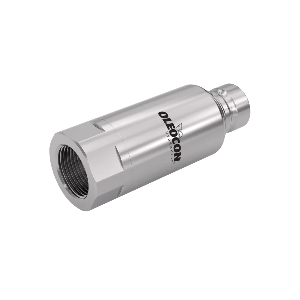
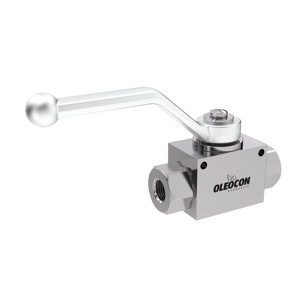
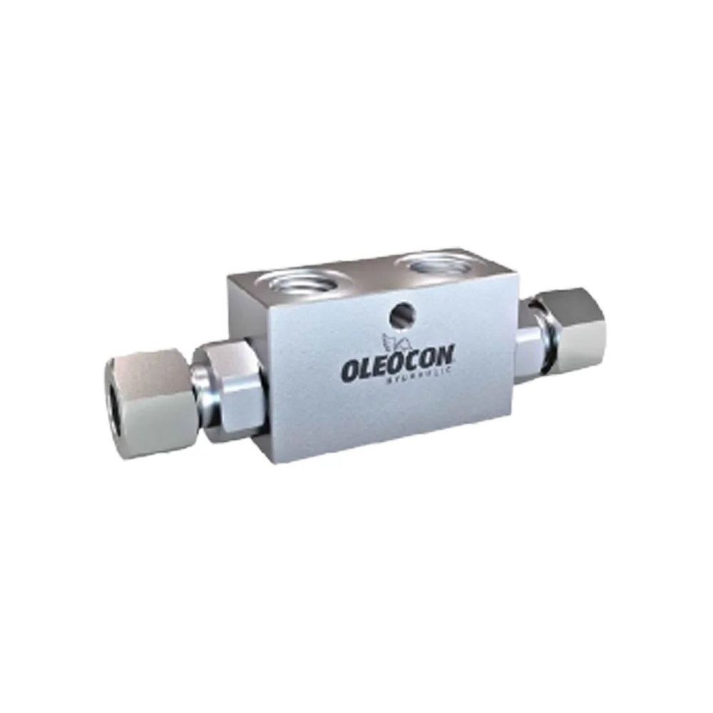
Double-acting pilot-operated check valve (twin locking)
Twin lock valve that locks the cylinder in both directions and shuts off flow unless pilot pressure is applied. Its internal parts are heat treated.
TLV · Metric connection
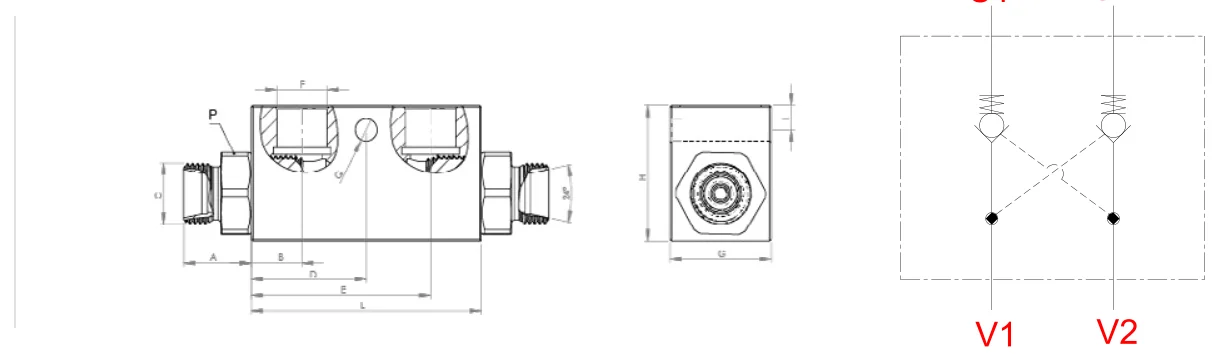
06–12Body size
2Connection type: Metric connection, BSPP connection
3Product code
Features and benefits
Technical specifications
- Operating temperature−20 °C/+100 °C
- Working pressureUp to 350 bar
- DimensionsMetric 12 L·1/4" – 1/2"
- Flow rateUp to 35 l/min·up to 50 l/min
- Thread optionsMetric·BSP
- SealNBR
- MaterialCarbon steel
Selection
How is the product code read?
TLV-10-G38
Thread
G = BSPP
Body size
10 06 12
Series
Twin lock valves
How it works
How does the valve work?
Locks both lines. When pressure arrives on one line, it opens the lock on the opposite line with pilot pressure; when the directional valve is centered, the cylinder stays where it is.
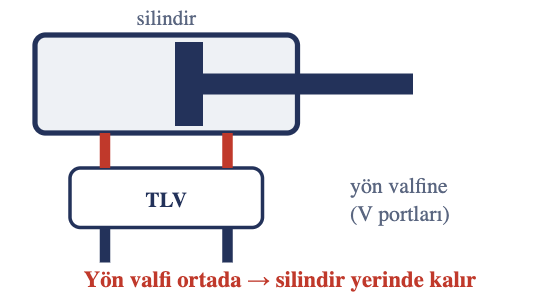
Locked
No pilot pressure: oil cannot leave the cylinder.
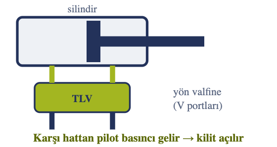
Open
When pressure arrives on one line, the lock on the opposite line is released.
Holds a load for a long time
Used to hold the load in position; unlike a check valve, it can release the cylinder when required.
For a double-acting cylinder
The twin lock valve holds both lines; for a single-acting cylinder, locking one line is enough.
Selection
How it differs from other auxiliary valves.
Scroll the table sideways to see all columns
| Valve | What does it do? | When? |
|---|---|---|
| FUV | Adjusts flow in one direction, free in the reverse | Cylinder speed in one direction only (e.g. lowering) |
| FCV | Adjusts flow rate in both directions | Cylinder / motor speed in both directions |
| CV | Allows flow in one direction only | Preventing backflow |
| TLV (this page) | Locks the cylinder in both directions | Holding a load in position for a long time |
| HPV | Shuts off flow if the hose bursts | Safety on load-lifting cylinders |
| PS-401 | Discharges excess pressure to the tank | Protecting the system from overload |
Instructions and warnings
Before use.
Correct use
For long life and reliable sealing
- Do not expose to abnormal operating conditions (for example oscillation, pressure shocks, water hammer, cavitation, solid and abrasive particles).
Warnings
Read before installation and use
- !Do not touch the valve when the operating temperature is below -20 °C or above +50 °C.
- !Make sure the system pressure is below the maximum working pressure.
- !Make sure all connection surfaces are clean so that dirt and dust do not build up in the circuit.
- !Make sure the mounting parts are on the same axis and fully connected.
- !Make sure the Oleocon product you have selected is suitable for your system's temperature, material and pressure requirements.
- !For any other questions, contact the Oleocon technical support team.
Installation and use
Filtration, viscosity, temperature.
Scroll the table sideways to see all columns
| Condition | Oleocon |
|---|---|
| Filtration | Pending |
| Viscosity | Pending |
| Oil temperature | −20 … +100 °C |
| Body | Pending |
Selection
One-way or two-way lock?
Scroll the table sideways to see all columns
| One-way lock | Two-way lock (TLV) | |
|---|---|---|
| What does it lock? | Holds the cylinder in one direction (e.g. to stop the load from lowering) | Holds the cylinder in place in both directions |
| Port | V1 / C1 + pilot | V1 V2 (valve side) · C1 C2 (cylinder side) |
| Oleocon | Pending | ✔ TLV |
Technical data
How much pressure is needed to release the lock?
The two most important values in a lock valve are the pilot ratio and the check valve opening pressure.
Scroll the table sideways to see all columns
| Code | Pilot ratio | Opening pressure | Maximum flow rate | Maximum pressure | Leakage |
|---|---|---|---|---|---|
| TLV-06-G14 | Pending | Pending | 35 l/min | 350 bar | Pending |
| TLV-10-M18 | Pending | Pending | Pending | 350 bar | Pending |
| TLV-12-G12 | Pending | Pending | 50 l/min | 350 bar | Pending |
What does pilot ratio mean?:
At a 4:1 ratio, opening the lock that holds a 200 bar load in the cylinder takes about 200 ÷ 4 = 50 bar of pilot pressure on the opposite line. The higher the ratio, the easier the lock opens, but heavy loads are lowered with less control.
Installation and use
A wrongly fitted valve is useless.
Caution
Do not mix up the V and C ports
V ports connect to the directional valve, C ports to the cylinder. A lock valve connected the wrong way round does not hold the cylinder.
Directional valve center position
In the center position A and B must be open to the tank; otherwise pilot pressure remains and the lock does not close fully.
Do not disassemble under load
The line between the locked cylinder and the valve is pressurized. Lower the load and release the pressure before disassembly.
Heated oil builds pressure
When the oil heats up in a locked cylinder, pressure rises; keep this in mind for machines left in the sun for a long time.
Installation and use
Port names and correct placement.
-
01
Install as close to the cylinder as possible
If the hose between the valve and the cylinder bursts, the lock is of no use.
-
02
V ports to the valve, C ports to the cylinder
If connected the wrong way round, the cylinder will not lock.
-
03
Flow control valve in between
If FUV is used, it is fitted between the cylinder and the TLV.
-
04
Directional valve center position
The center position of the directional valve used with the lock valve must open A and B to the tank; otherwise the lock does not close fully.
FAQ
The questions users ask most.
How long does it hold the load?
With the valve closed, no oil passes; the load lowering is usually caused by a leak in the cylinder seal.
How is it used together with a flow control valve?
FUV is fitted between the cylinder and the TLV.
Which directional valve should it be used with?
With a directional valve whose A and B lines are open to the tank in the center position; otherwise the lock does not close fully.
What seal does it have?
Standard NBR; for mineral-based hydraulic oil.
Can't find your question?Our technical team answers every question about the series.Contact technical support
Applications
Where is TLV used?
Downloads
Catalogs, Technical Data and CAD.
You may also like
Related series
Can't find the size or connection you need in the list?
Send us the code or a technical drawing; we will get back to you with a suitable product and price.