
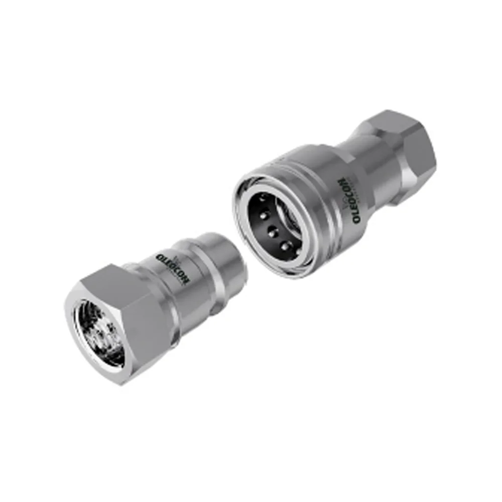
 Poppet type
6,3–50315bar
ISO 7241-A / B
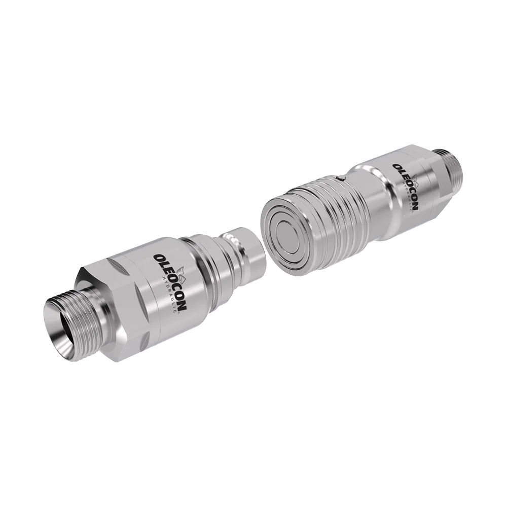
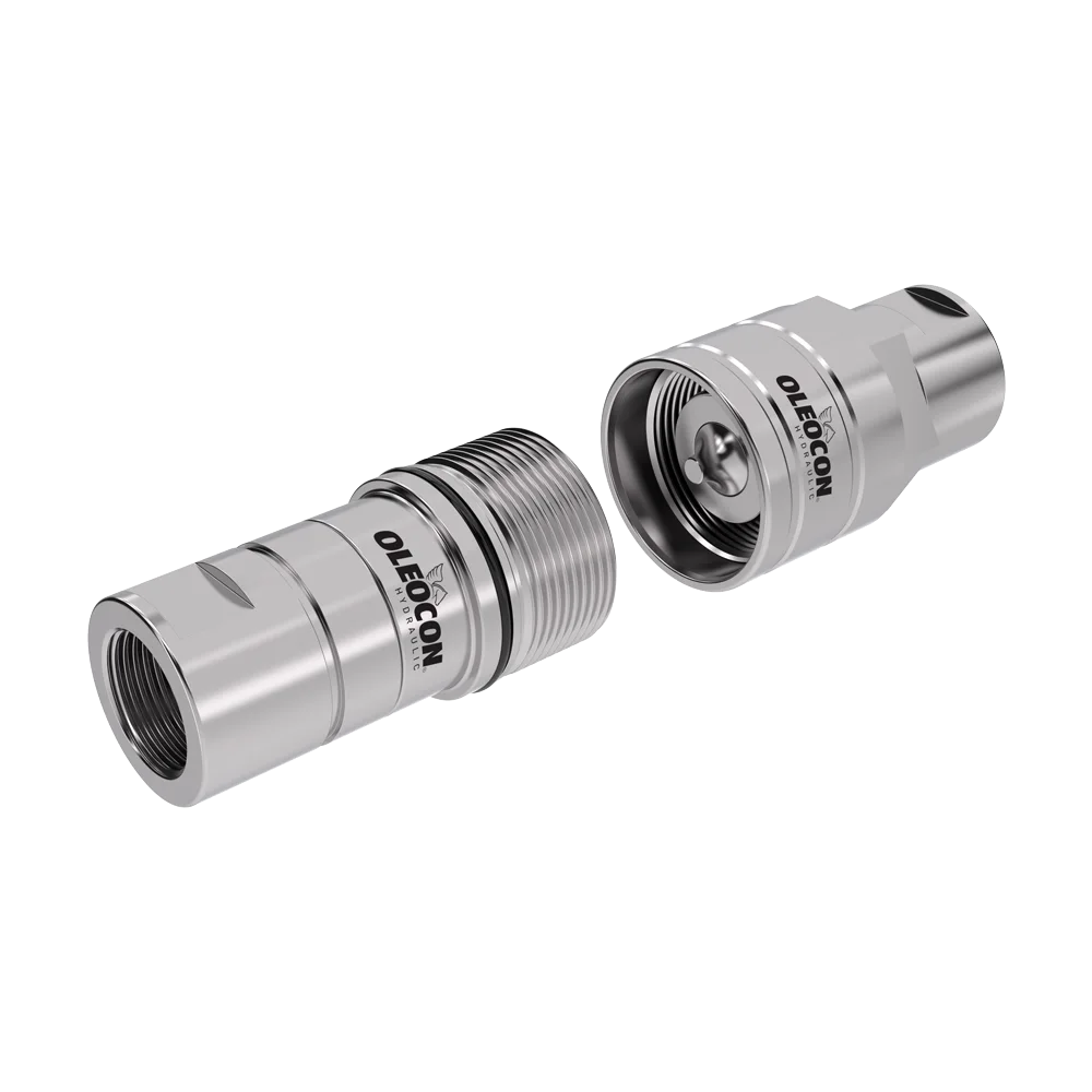
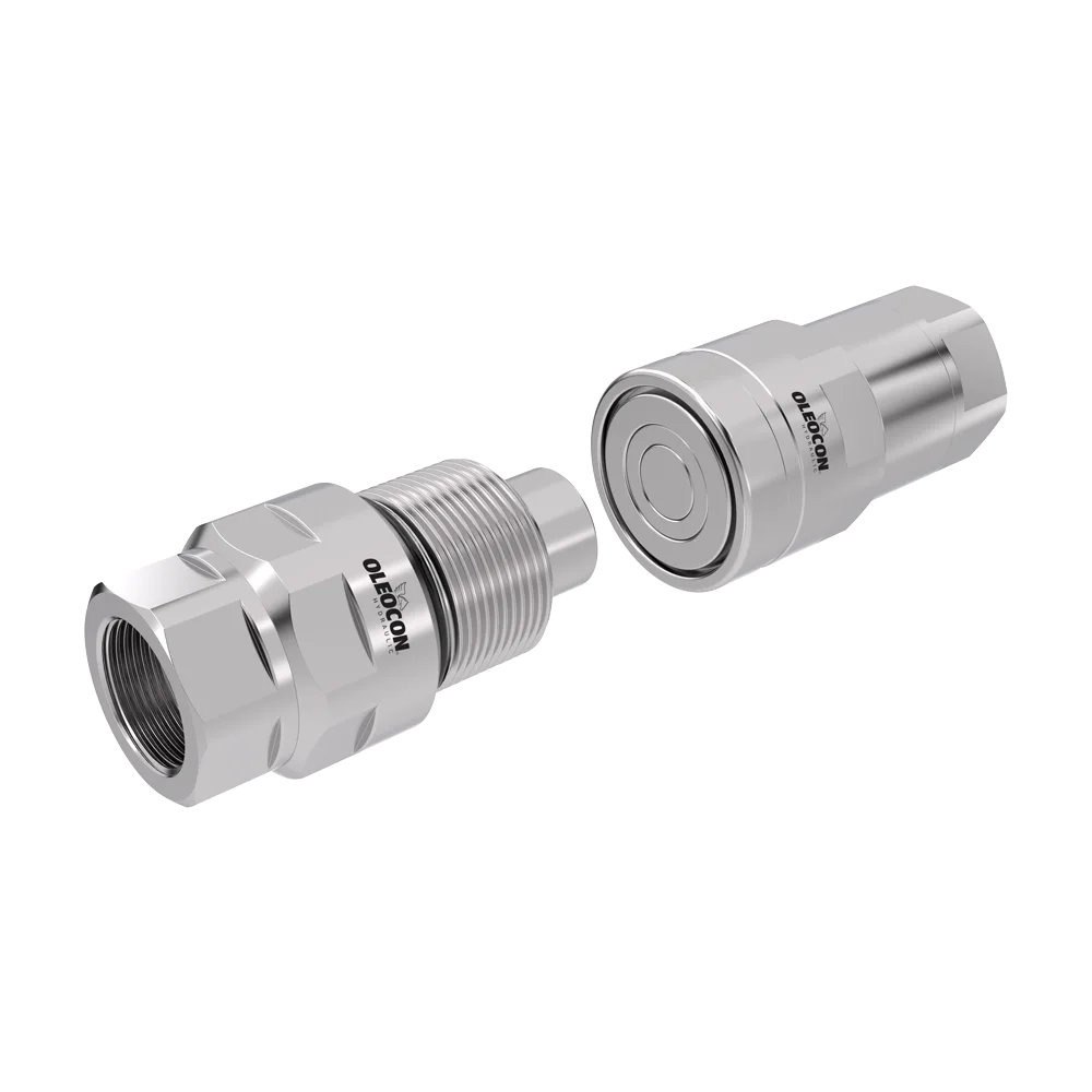
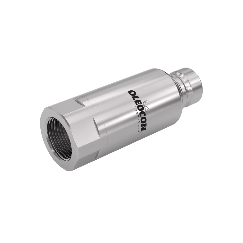
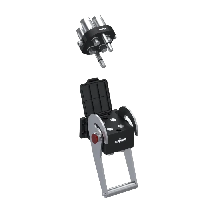
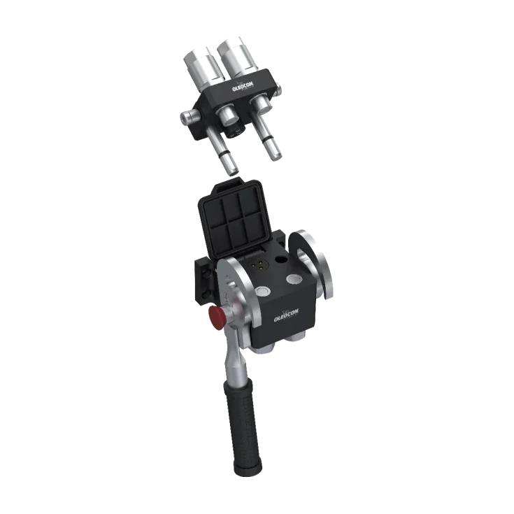
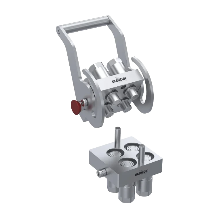
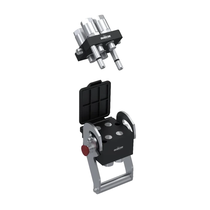
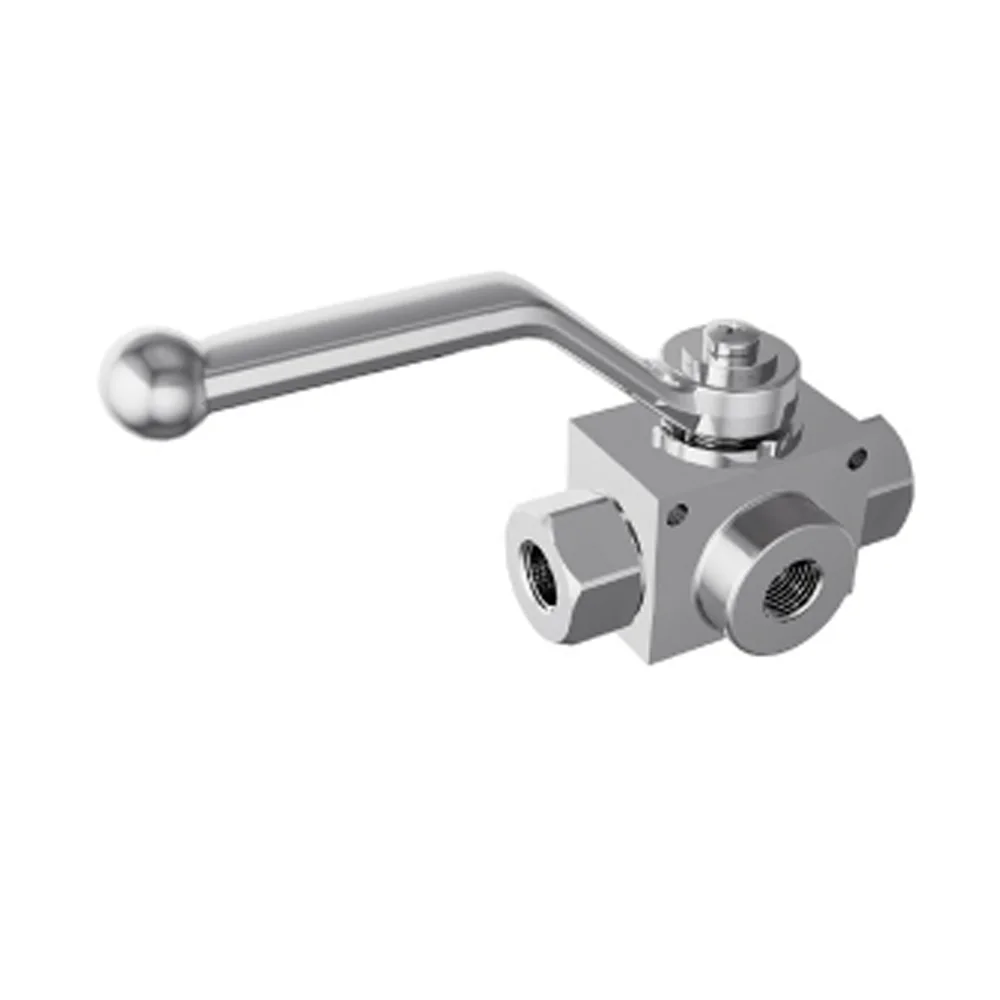
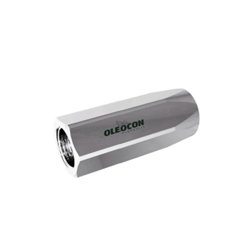
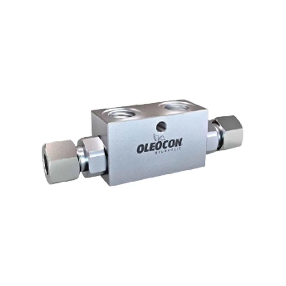
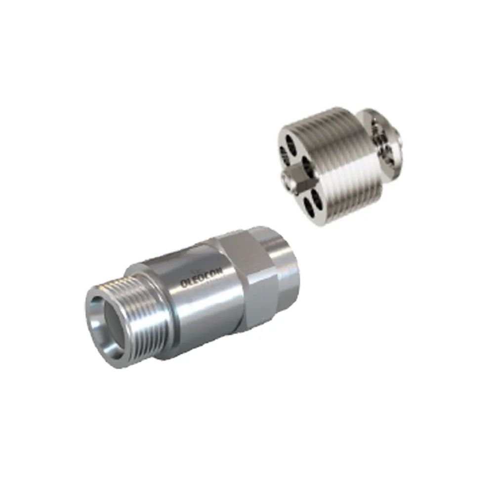
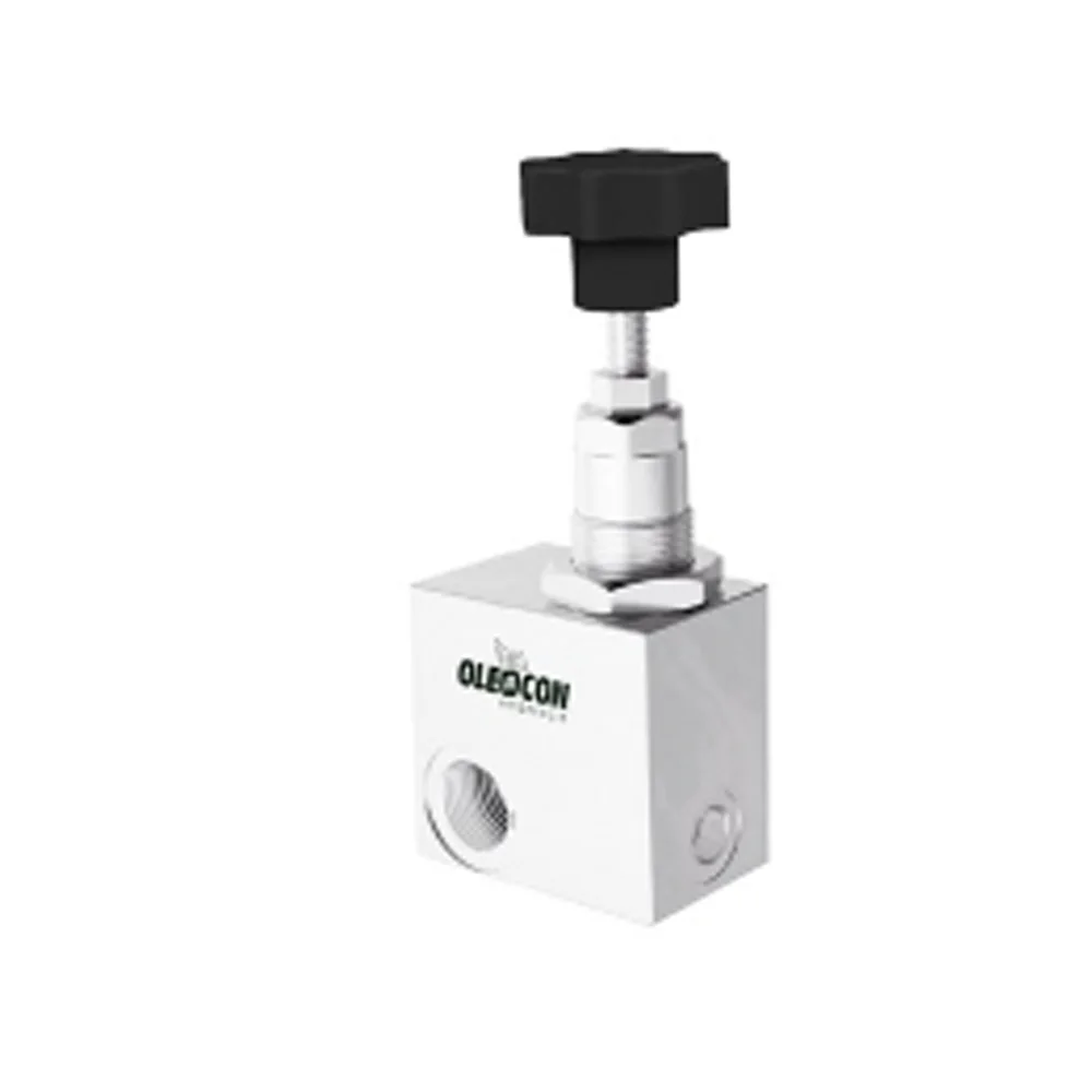
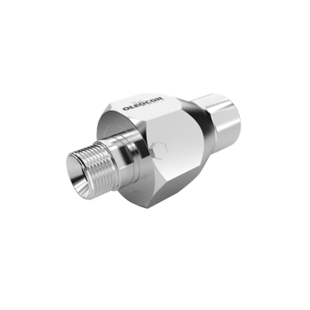
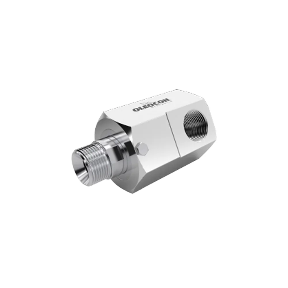
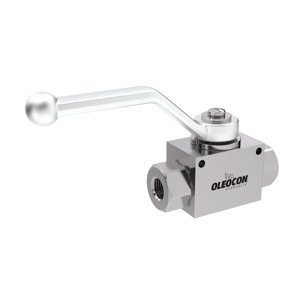
Ball valve · 2-way
KV2
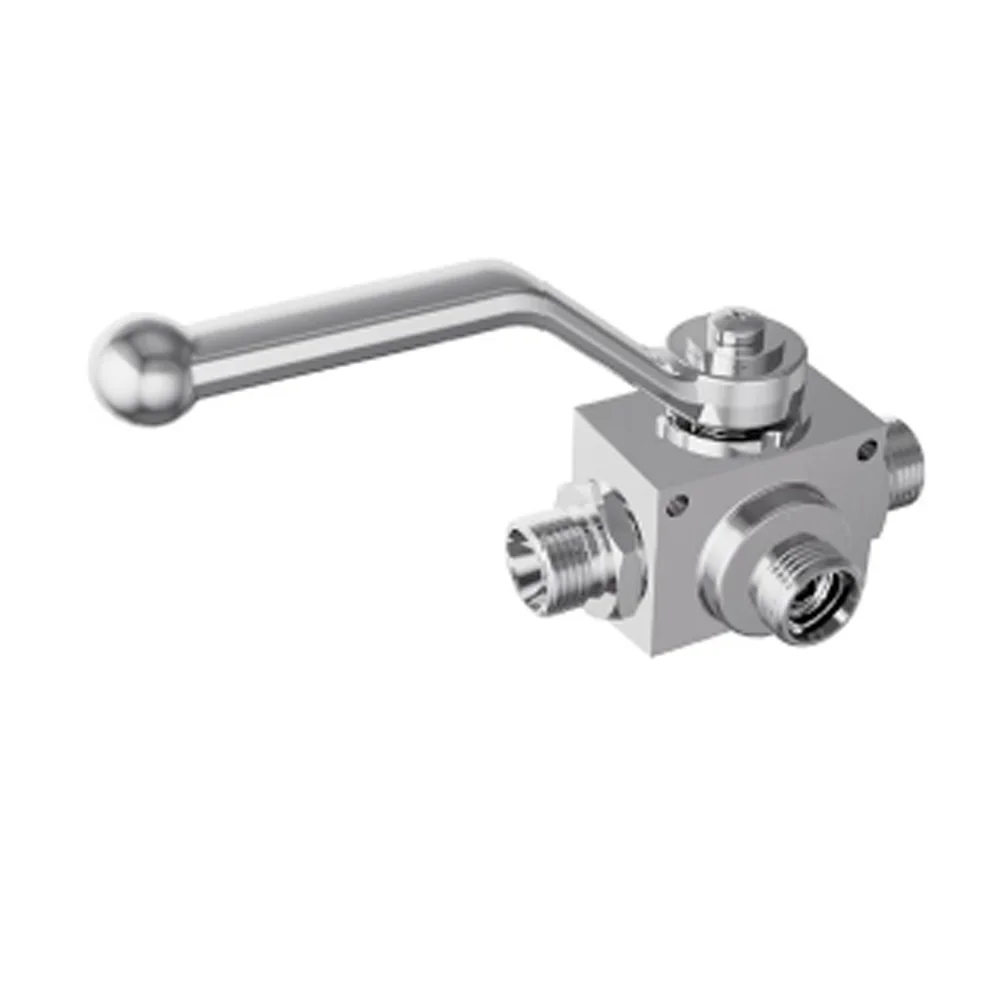
2-way high-pressure ball valve
A 2-way hydraulic ball valve that opens and closes the flow path. It does not restrict flow, its full-bore design prevents cavitation, and it can be locked open or closed with the locking plate.
KV2 · BSPP female thread
500barMax. working pressure
DN10–25Body size
2Connection type: BSPP female thread, Metric
40Product code
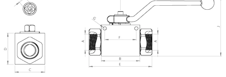
Dimensions for the NPT, metric and UNF male types are not given in the catalogue; you can request technical data. Request technical data
Features and benefits
Technical specifications
- Operating temperature−20 °C/+100 °C
- Working pressureUp to 500 bar
- Body sizesDN10-25
- MaterialHigh-strength·Carbon steel·Stainless steel
- Thread optionsBSP/NPT/SAE/Metric
- SealNBR/FKM/PTFE/EPDM
How it works
Where does the oil flow in each lever position?
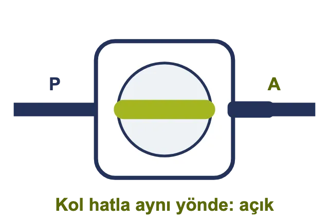
Open (P → A)
Oil passes unobstructed.
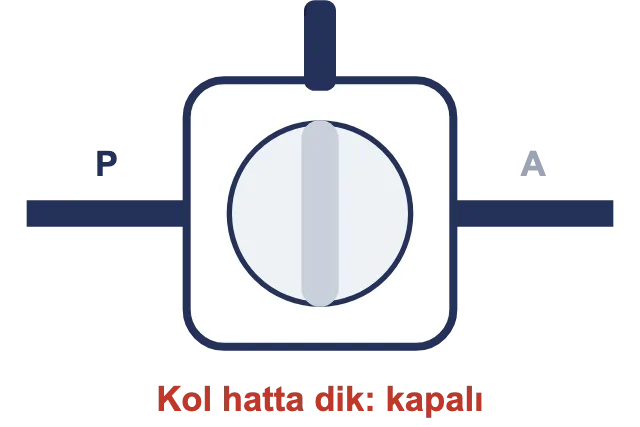
Closed
Flow is shut off completely.
Intermediate position
With the lever between the two positions, the valve is half open; do not leave it in this position and do not use it to adjust flow.
Lever direction
With the lever in line with the pipe, the valve is open; at right angles to the line it is closed; the position can be read from outside.
Selection
How to read the product code
KV2-10-G14
Thread
G = BSPP NPT SAE = UNF 6L–42L / 6S–38S = DIN 2353 metric tube
Body size
10 12 (DN12,5) 20 25
Series
2-way ball valve
Performance
Choose a body size and see what it handles.
The maximum working pressure of each body size.
Max. working pressure
DN10
500bar
7252 psi
In this series 400 – 500 bar
| Body size | Max. working pressure |
|---|---|
| barpsi | |
| DN10 | 500 / 7252 |
| DN12,5 | 500 / 7252 |
| DN20 | 400 / 5802 |
| DN25 | 400 / 5802350 bar: KV2-25-G112, KV2-25-NPT114, KV2-25-NPT112 |
Technical data
Each body size has its own pressure limit.
Valves with larger bodies withstand lower pressure. When the seal changes, the limit changes too.
Scroll the table sideways to see all columns
| Body size | Thread examples | Maximum working pressure | Test pressure | Weight |
|---|---|---|---|---|
| DN10 | G 1/4 · G 3/8 · 7/16-20 UNF · M12–M20 | 500 bar | Pending | 0.40 – 0.47 kg |
| DN12.5 | G 1/2 · 3/4-16 UNF · M22–M26 | 500 bar | Pending | 0.60 – 0.62 kg |
| DN20 | G 3/4 · 1 1/16-12 UN · M30 | 400 bar | Pending | 1.25 – 1.30 kg |
| DN25 | G 1 – G 1 1/2 · 1 5/16 – 1 7/8 UN · M36–M52 | 400 bar350 bar for 1 1/4″ and 1 1/2″ class connections | Pending | 1.36 – 2.49 kg |
Scroll the table sideways to see all columns
| Seal | Maximum pressure | Temperature | Suitable fluid |
|---|---|---|---|
| NBR (standard) | Pending | −20 / +100 °C | Mineral-based hydraulic oil |
| FKM | Pending | Pending | High temperature, fuel, synthetic oil |
| PTFE | Pending | Pending | Almost any hydraulic fluid |
| EPDM | Pending | Pending | Water-glycol, phosphate ester fluid (not used with mineral oil) |
Technical data
How much force is needed to turn the handle?
This information is needed to select the lever length for manual operation, or the actuator size for actuated operation.
Scroll the table sideways to see all columns
| Body size | 0 bar | 100 bar | 250 bar | Maximum pressure |
|---|---|---|---|---|
| DN10 | Pending | Pending | Pending | Pending |
| DN12.5 | Pending | Pending | Pending | Pending |
| DN20 | Pending | Pending | Pending | Pending |
| DN25 | Pending | Pending | Pending | Pending |
Installation and use
Lock, limit switch, actuation.
Locking plate
Locks the valve in the open or closed position
Padlockable lever
Prevents unauthorized opening during maintenance
Limit switch
Signals electrically whether the valve is open or closed
Pneumatic actuator
Opens and closes the valve remotely by air
Electric actuator
Opens and closes the valve by motor
Different handle type
Short or angled handle for tight spaces
Stainless steel body / ball
Marine, food, corrosive environments
Warnings
What not to do with a ball valve.
CautionMost complaints from the field come from these points.
Do not leave in an intermediate position
Always move the lever fully open or fully closed, between the stops. A valve left in an intermediate position damages its seat.
Turn carefully under pressure
Closing suddenly at high pressure creates a pressure surge in the line. Turn the handle slowly in a single movement.
Valve left unused for a long time
On the first turn after a long idle period, the handle feels stiffer. Open and close the valve at regular intervals.
Instructions and warnings
Before use.
Correct use
For long life and reliable sealing
- Keep the flow rate within normal valuesMake sure the flow rate is within normal values.
- Protect against abnormal conditionsDo not expose to oscillation, pressure shocks, water hammer, cavitation, or solid and abrasive particles.
- Use fully open or fully closedA ball valve works fully open or fully closed; in a half-open position the ball seat wears and sealing is lost. Use FUV / FCV for flow adjustment.
- Turn the handle all the way to the stopsAlways turn the lever between the stops to the fully open or fully closed position; the ball seat of a valve left in an intermediate position will be damaged.
- Turn slowly under pressureClosing suddenly at high pressure creates a pressure surge in the line; turn the handle slowly and in a single movement.
- Operate the valve from time to timeAfter a long period of inactivity, the handle feels stiffer the first time it is turned; open and close the valve at regular intervals.
Warnings
Read before installation and use
- !Do not touch the valves when the operating temperature is below -20 °C or above +50 °C.
- !Make sure the system pressure is below the maximum working pressure.
- !Make sure all connection surfaces are clean so that dirt and dust do not build up in the circuit.
- !Make sure the mounting parts are on the same axis and fully connected.
- !Make sure the Oleocon product you have selected is suitable for your system's temperature, material and pressure requirements.
- !For any other questions, contact the Oleocon technical support team.
Quality
Every valve is tested before shipment.
- Every valve undergoes a pressure test (test pressure and duration)
- Material certificate (EN 10204 3.1) on request
- Marine / maritime approvals (DNV, ABS, BV)
- ISO 9001 quality management
- Place of manufacture: Konya, Türkiye
FAQ
Most frequently asked questions.
What is the difference between a 2-way and a 3-way valve?
A 2-way valve (KV2) opens or closes a single line. 3-way valves (KV3L, KV3T) direct flow from the inlet to different outlets.
What is the maximum working pressure in bar?
Varies by body size: 500 bar for DN10 and DN12.5, 400 bar for DN20 and DN25, 350 bar for the 31.5 and 40 types of DN25. The stainless steel version is in the 250–400 bar range.
Can it be used for flow rate adjustment?
No. The ball valve works at the full positions between the stops; in an intermediate position the ball seat wears and the seal is compromised. Use FUV or FCV series flow control valves for flow rate adjustment.
Which seal should I choose?
The standard seal is NBR and is used for mineral-based hydraulic oil. FKM and EPDM are optional; FKM is standard on stainless steel valves. Confirm suitability with technical support.
Is there a stainless steel option?
Yes. The AISI 316L stainless steel version is used in the −20 °C / +200 °C range at 250–400 bar.
Can the valve be locked in the desired position?
Yes. By changing the position of the locking plate, the valve can be locked in the desired position.
What thread types are available?
Versions are available with BSPP, NPT, UNF (SAE) and metric tube connections (light and heavy series).
Can't find your question?Our technical team answers every question about the series.Contact technical support
Applications
Applications
Downloads
Downloads
You may also like
Related series
Can't find the size or connection you need in the list?
Send us the code or a technical drawing; we will get back to you with a suitable product and price.