
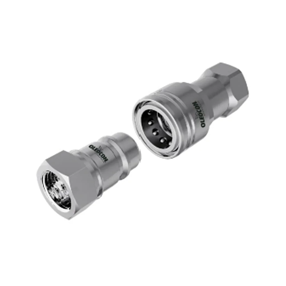
 Poppet type
6,3–50315bar
ISO 7241-A / B
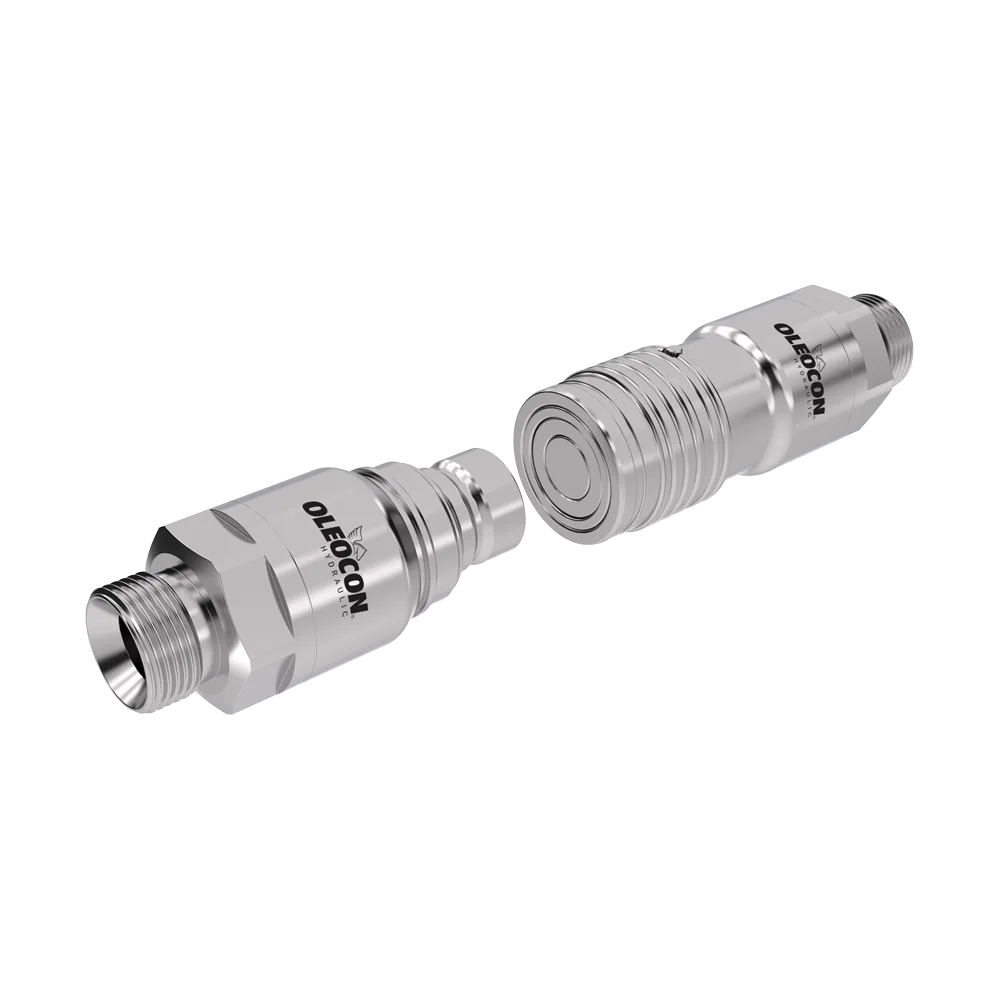
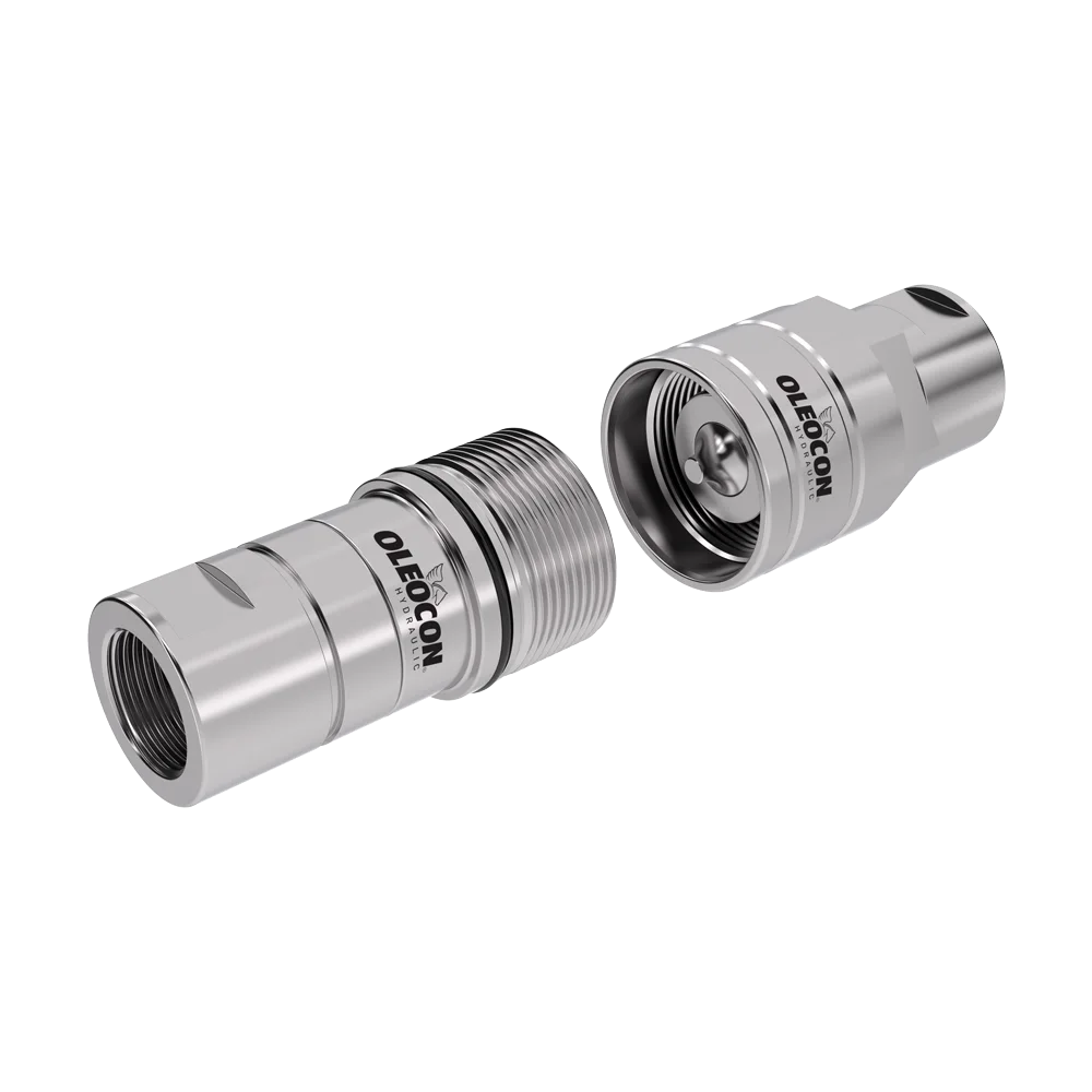
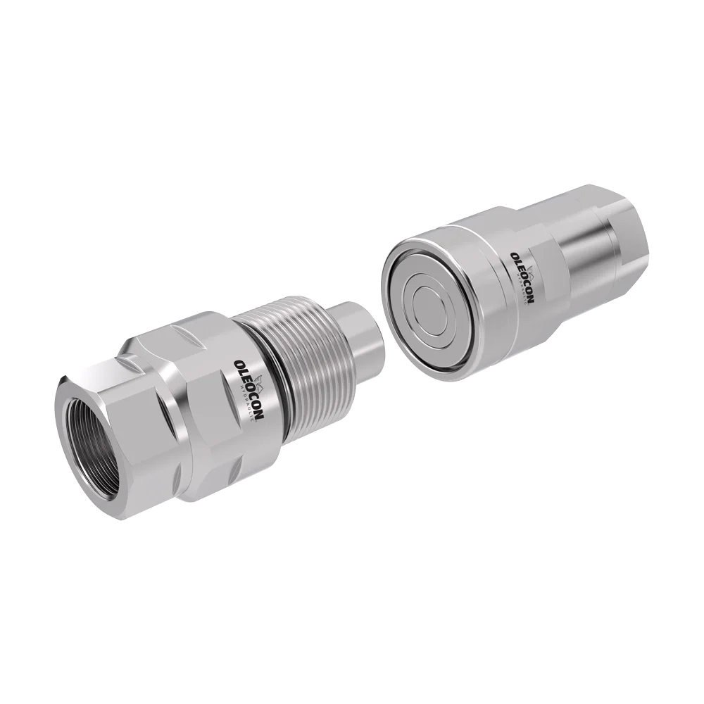
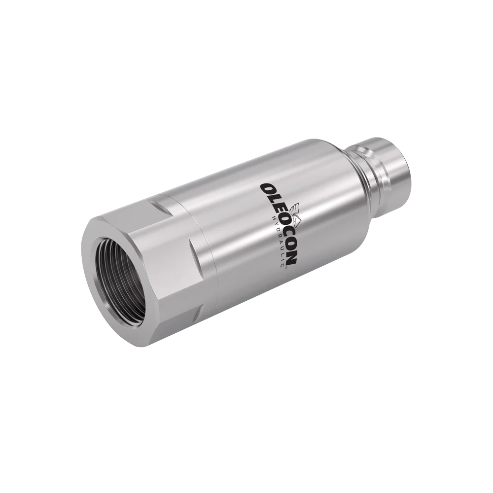
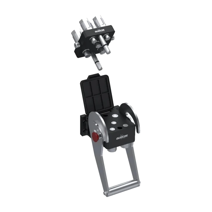
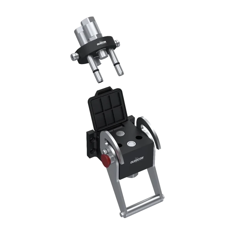
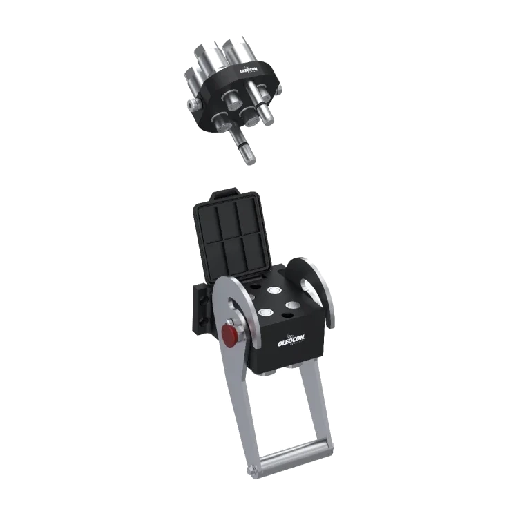
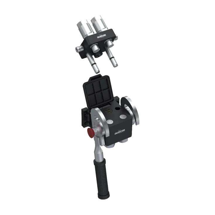
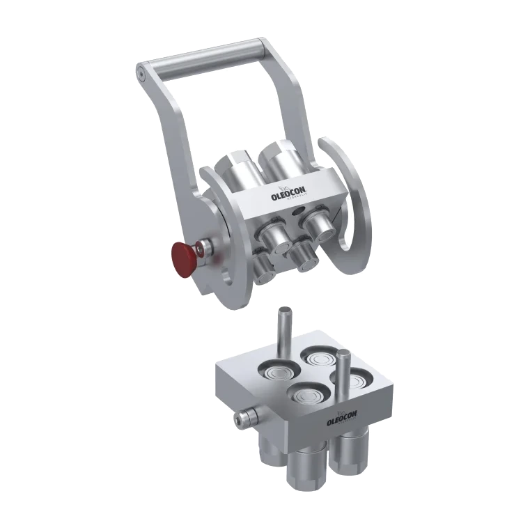
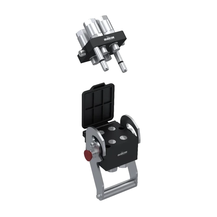
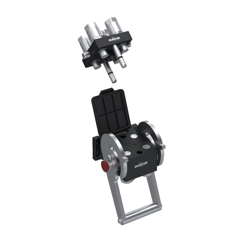
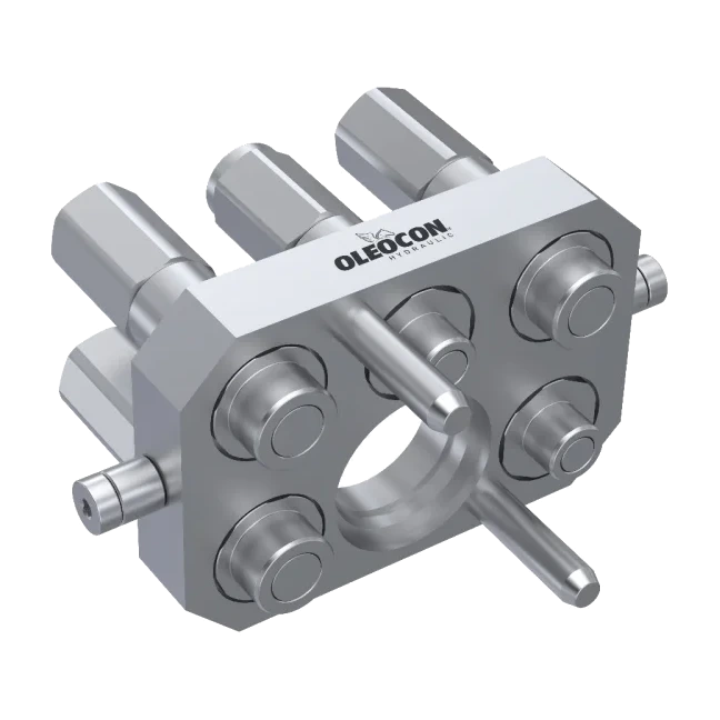
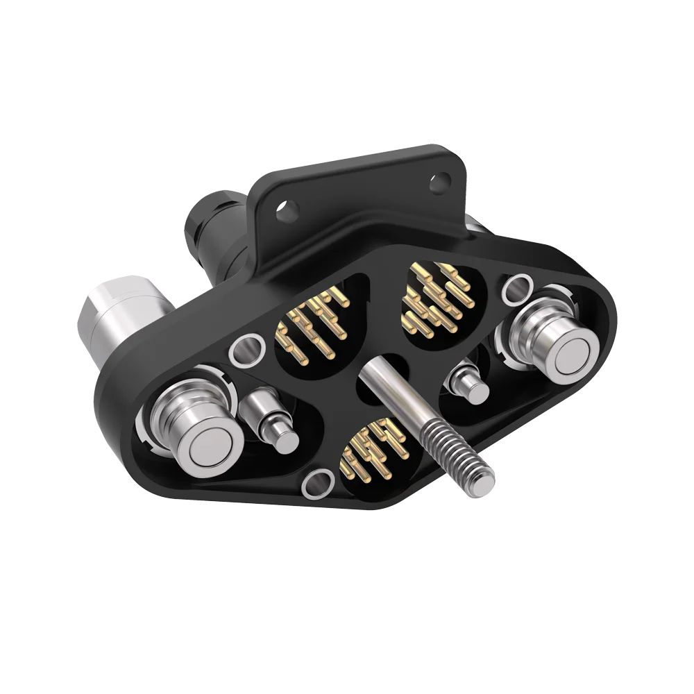
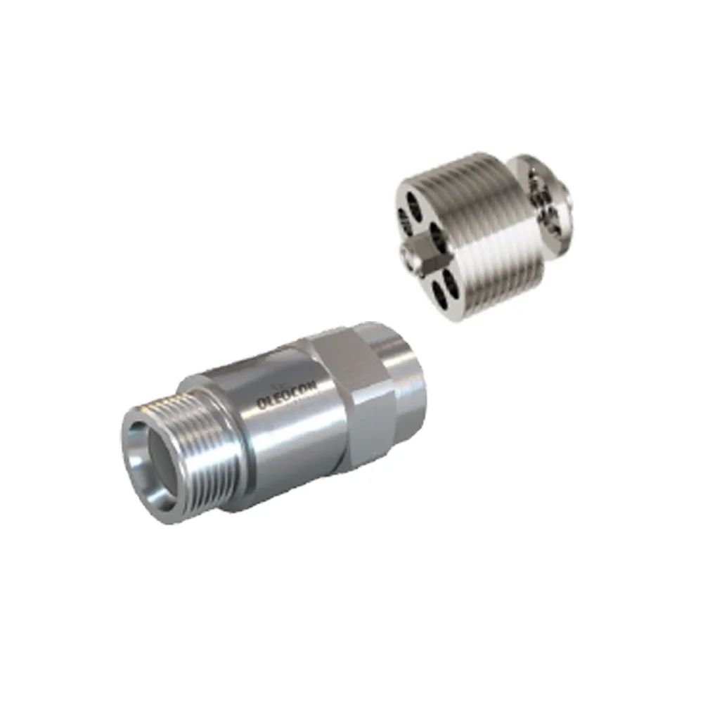
Multicouplings
H4P
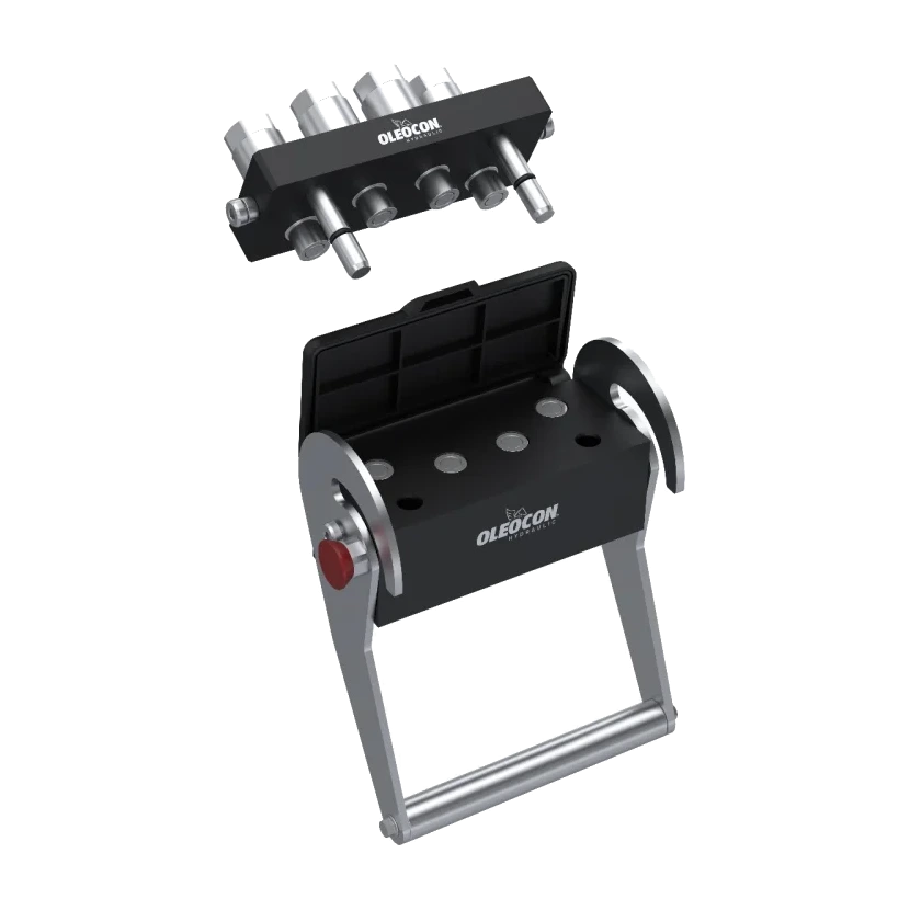
Multicoupling
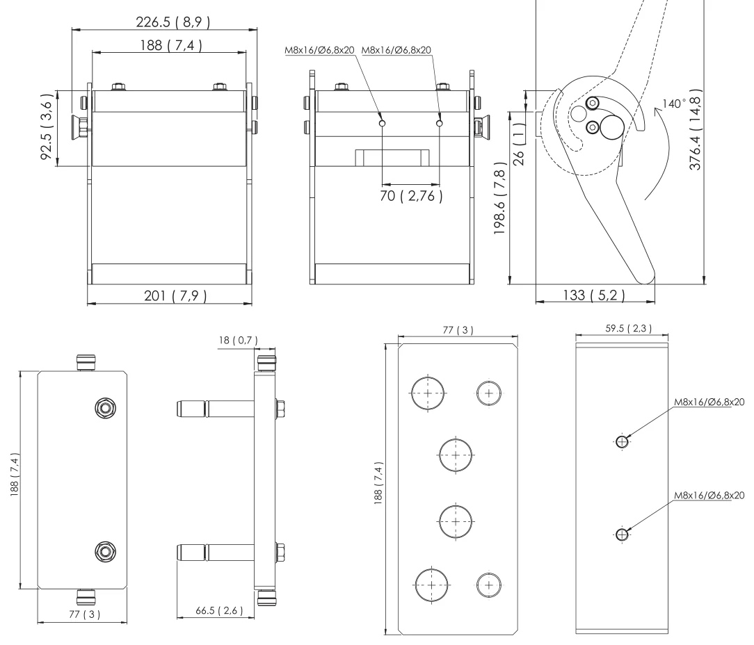
Multicoupling that connects 4 lines with a single lever movement. Its flat face couplings keep dirt out of the circuit; it can be connected from both sides under residual pressure.
H4P
10Body size
10Product code
Features and benefits
Technical specifications
- CompatibilityMarket standard
- Mechanical connectionInternal cams and locking pins
- Disconnection typeBy turning the lever after the locking system is released
- Under residual pressureCan be connected from both sides
- Thread optionsBSPP·NPT·SAE·Metric
- Valve typeFlat face
- Working pressureUp to 350 bar (5000 psi)
- Operating temperature−20 °C/+100 °C
Selection
How is the product code read?
H4P–F–I–DC
Thread
DC / DB / LY / UP / PP / HC Thread: G1/2 G3/8 M22×1,5 (15L) 13/16-16 UN male UN swivel nut
Line layout
I / G Line layout: I = 4 × 10 couplings G = 2 × 10 couplings
Connection side
F / M Female (machine) / male (attachment) half
Series
H44 multicoupling
Technical data
Pressure, flow rate and leakage value of each coupling size.
Scroll the table sideways to see all columns
| Coupling size | Working pressure | Burst pressure | Flow rate | Leakage per connection | Connect under residual pressure |
|---|---|---|---|---|---|
| 10 (3/8″) | Pending | Pending | Pending | Pending | Pending |
Technical data
Performance by line layout.
The number and size of couplings on the plate determine the total flow rate the plate can carry and the connection force.
Scroll the table sideways to see all columns
| Line layout (code) | Couplings | Working pressure | Total flow rate | Connecting lever force |
|---|---|---|---|---|
| I | 4 × 10 | Pending | Pending | Pending |
| G | 2 × 10 | Pending | Pending | Pending |
Technical data
Pressure drop by flow.
Pressure drop across the coupling for each body size. Select a body size; hover over the chart to read a value or enter your flow rate.
10From another seriesQCF series coupling data (measured); extra loss in the plate body is not included.
Source
From another series
l/min
- 10 2.1 bar31 PSI
Read from each size’s curve; sizes outside their curve show “out of range”.
Technical data
How much force can the plate withstand?
Scroll the table sideways to see all columns
| Value | Description | Oleocon |
|---|---|---|
| Maximum mechanical strength of the plate | The total separation force of the pressurized lines must not exceed this value | Pending |
| Lever force when connecting | Force needed to turn the lever under residual pressure | Pending |
| Lever rotation angle | The angle through which the lever turns to the connected position | Pending |
Calculation:
Separation force (N) ≈ the sum, for each pressurized line, of pressure (bar) × cross-sectional area (cm²) × 10. This value must remain below the strength of the plate.
Installation and use
The plate can be renewed piece by piece.
Scroll the table sideways to see all columns
| Kit | What is it for? | Oleocon code |
|---|---|---|
| Female half / male half | To take only the machine side or only the attachment side | F / M letter in the code (H4P-F-…, H4P-M-…) |
| Single coupling (spare) | Replacing a single damaged line | Pending |
| Seal kit | Renewing the seals of a leaking coupling | Pending |
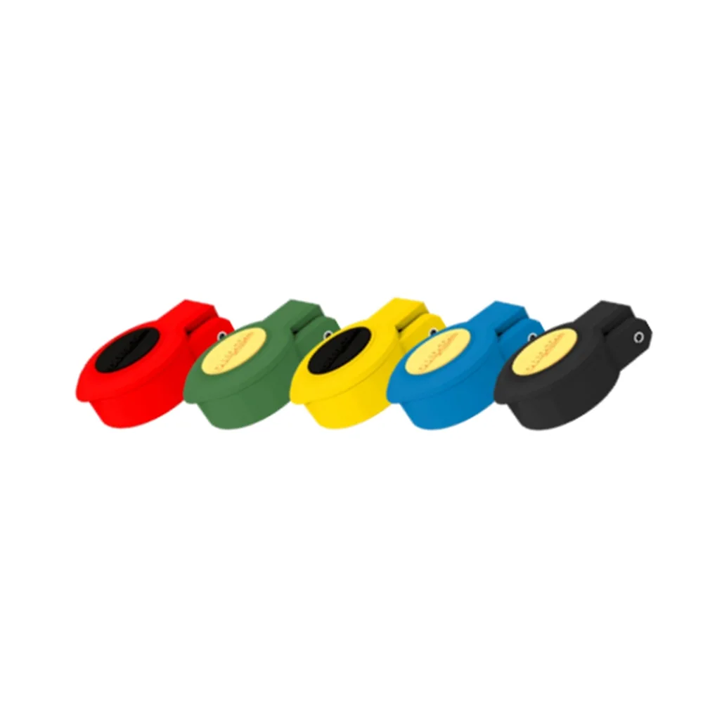
| Dust cap | Protecting couplings from dirt when disconnected | Pending |
| Parking station | Keeping the detached attachment side on the machine | Pending |
| Lever and safety lock | Replacing a broken or lost lever | Pending |
| Guide pins · screws and plugs | Mounting and closing off unused lines | Pending |
| Electrical connection module | Connecting the electrical signal together with the hydraulics | Pending |
Instructions and warnings
Before use.
Correct use
For long life and reliable sealing
- Before connecting, clean the mating surfaces of all couplings on the plate so that dirt does not enter the system.
- Align the two plates on the same axis and make sure the lever is locked all the way.
- Do not expose to abnormal operating conditions (for example oscillation, pressure shocks, water hammer, cavitation, solid and abrasive particles).
Warnings
Read before installation and use
- !Do not connect or disconnect while there is flow in the lines (under dynamic pressure).
- !Do not touch the plate when the operating temperature is below -20 °C or above +50 °C.
- !Make sure the system pressure is below the maximum working pressure (350 bar).
- !Protect separated plates from dirt and dust; do not connect with a dirty surface.
- !Make sure the Oleocon product you have selected is suitable for your system's temperature, material and pressure requirements.
- !For any other questions, contact the Oleocon technical support team.
Warnings
Points to watch with a multicoupling.
Caution
Do not force the handle
Do not turn the lever without releasing the safety lock. Do not use an extension pipe or tool to make the lever easier to turn.
Arrange pressurized and unpressurized lines in order
Placing pressurized and unpressurized (return) lines alternately on the plate extends seal life.
Check the pressure of each line
The lowest-pressure coupling on the plate determines the system limit.
Fit the dust cap when disconnected
A contaminated coupling damages the seal when connected.
Applications
Where is H4P used?
Downloads
Catalogs, Technical Data and CAD.
You may also like
Related series
Can't find the size or connection you need in the list?
Send us the code or a technical drawing; we will get back to you with a suitable product and price.